Caution – Yaskawa 120 Series I/O Modules User Manual
Page 205
5.2 Register Output Specifications
5-7
5
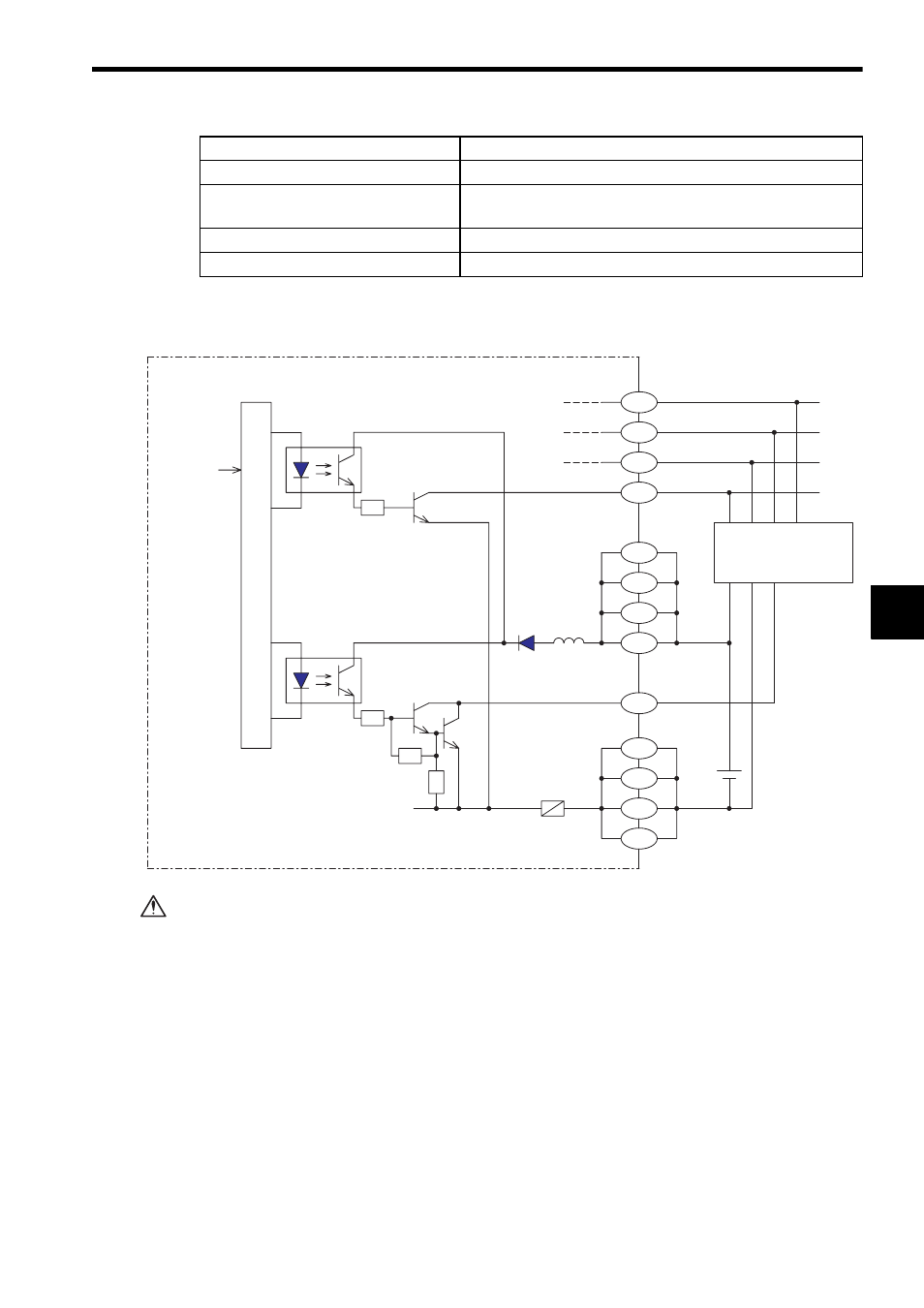
2) The following diagram shows the circuit configuration.
Do not replace the built-in fuses of the Register I/O Modules.
If the built-in fuses are replaced by anyone other than a Yaskawa-approved
technician, a failure or malfunction may occur in the Register I/O Modules, and
the guarantee is void.
Note: (1) The following pins of CN1 are internally connected: The pins A1, B1, A11, and
B11, and the pins A2, B2, A12, and B12.
Also connect these pins externally. Not connecting these pins externally may
cause malfunction of GL120 and GL130.
(2) External connection connector (included)
Connector: FCN-361J040-AU (soldered) (made by Fujitsu Ltd.)
Cover: FCN-360C040-B (made by Fujitsu Ltd.)
(3) Recommended wires
Use 0.26 mm
2
(AWG23) wires for connections between the connector pins.
Maximum Heat Value
3.5 W
Hot Swapping
(Removal/insertion under power)
Permitted
Approx. Mass
300g
External Dimensions
40.3
×130×103.9 mm (W×H×D)
Item
Specifications
DATA4
DATA3
DATA2
DATA1
From CPU
Internal circuits
Photo-
coupler
Connector CN1
Pin No.
Fuse
12/24VDC
Photo-
coupler
LED indicator
(with latch)
+12/24V
+
-
B20
A20
B19
A19
A11
B11
A1
B1
SEL1
B10
0V
A12
B12
A2
B2
+
-
Latch
CAUTION