4 precautions on wiring, 1 ac input modules, 1) power supply phasing for input signals – Yaskawa 120 Series I/O Modules User Manual
Page 259: 2) connecting inductive loads, Caution
6 Installation and Wiring
6.4.1 AC Input Modules
6-32
6.4
Precautions on Wiring
6.4.1 AC Input Modules - - - - - - - - - - - - - - - - - - - - - - - - - - - - - - - - - - - - 6-32
6.4.2 AC Output Modules - - - - - - - - - - - - - - - - - - - - - - - - - - - - - - - - - - - 6-35
6.4.3 DC Input Modules - - - - - - - - - - - - - - - - - - - - - - - - - - - - - - - - - - - - 6-40
6.4.4 DC Output Modules - - - - - - - - - - - - - - - - - - - - - - - - - - - - - - - - - - - 6-45
6.4.5 Connections between AC I/O Modules - - - - - - - - - - - - - - - - - - - - - 6-49
6.4.6 Connections between DC I/O Modules - - - - - - - - - - - - - - - - - - - - - 6-50
6.4.7 Analog Input Modules - - - - - - - - - - - - - - - - - - - - - - - - - - - - - - - - - 6-50
6.4.8 Analog Output Modules - - - - - - - - - - - - - - - - - - - - - - - - - - - - - - - - 6-51
6.4.9 External Power Supplies - - - - - - - - - - - - - - - - - - - - - - - - - - - - - - - 6-52
6.4.1
AC Input Modules
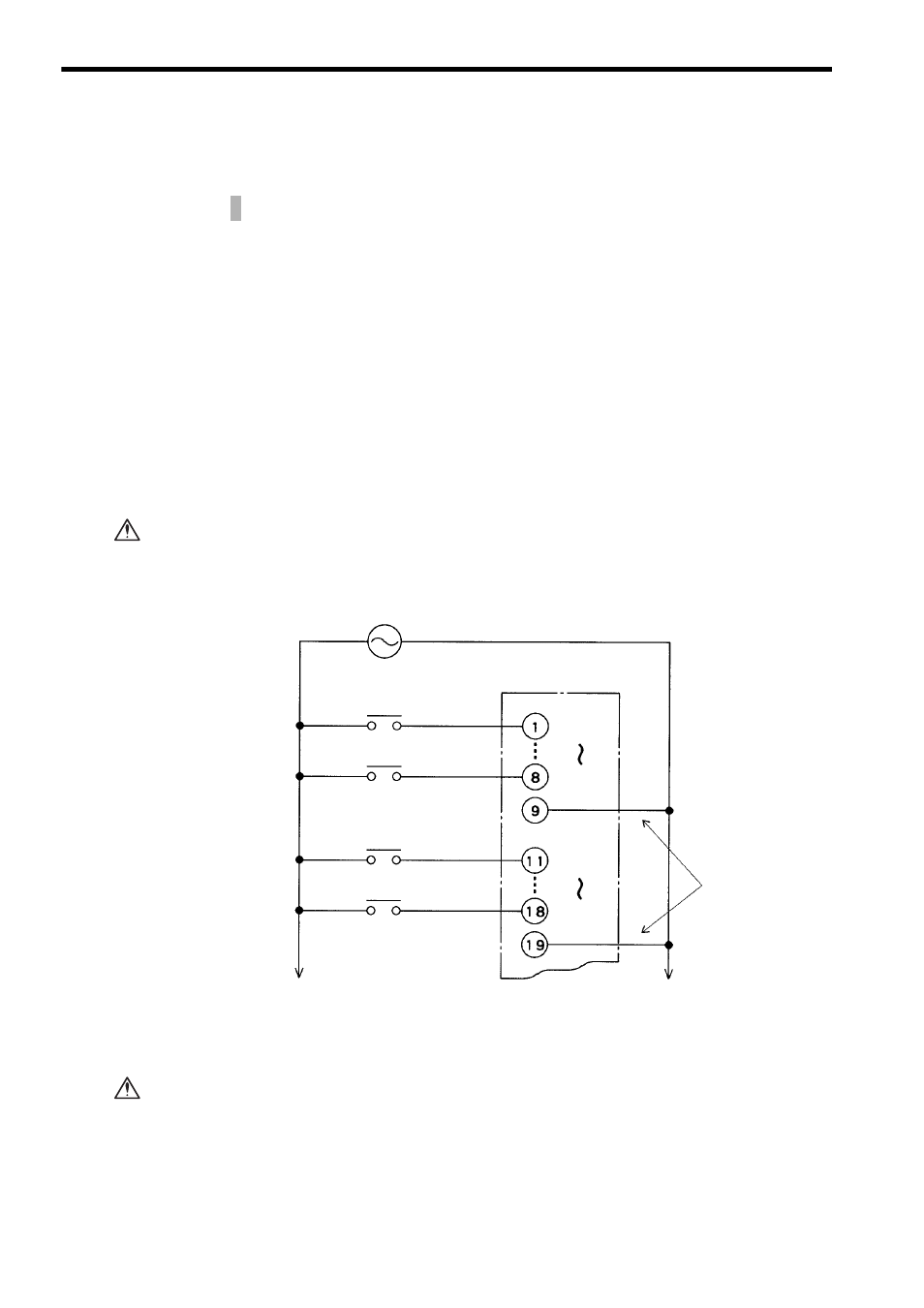
1) Power Supply Phasing for Input Signals
Connect power supplies of the same phases to the common 1 and common 2 of the
AC I/O Module.
If power supplies of different phases are connected, overheating or fire may
occur.
Fig. 6.8 Power Supply Phasing for Input Signals
2) Connecting Inductive Loads
If connecting an inductive load in parallel with AC Input Module, connect the surge
absorber in parallel with the inductive load to prevent surge voltage.
Failure to connect a surge absorber may result in damage to the AC Input Mod-
ule.
This section describes precautions when using 120-series I/O Modules.
CAUTION
Connect power
supply with the
same phase.
100 VAC
(200 VAC)
Input 1
Input 8
Common 1
Input 9
Input 16
Common 2
CAUTION