2 digital input module i/o allocation screen – Yaskawa 120 Series I/O Modules User Manual
Page 137
3.5 Operations Using MEMOSOFT
3-107
3
3.5.2
Digital Input Module I/O Allocation Screen
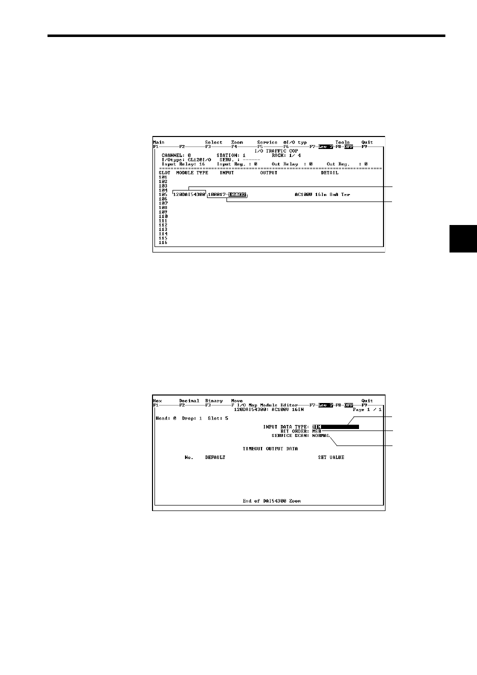
This section provides information on the MEMOSOFT I/O Traffic Cop Screen and
the Parameter Setting Screen.
1) The I/O Traffic Cop (i.e., I/O Allocation) Screen
Fig. 3.15 I/O Traffic Cop Screen
a) Module Type
Enter the Digital Input Module type, for example, 120DAI54300.
b) Set the I/O references to be used by the Digital Input Module.
When the first reference number is input, the cursor will move to the field for the last
reference number and the last reference number will be displayed automatically,
indicating the reference number that can be input. Press Enter Key to accept the
value, or change it to the desired value, if required.
2) The Parameter Setting Screen (Zoom)
Fig. 3.16 Parameter Setting Screen
a) Data Type
If an input register is set as the I/O reference number, data input can be set to BIN
(binary) or BCD (binary coded decimal notation).
b) Bit Order (LSB/MSB)
I/Os can be processed by handling data either in ascending or descending order of
the bit.
c) Service Scan (Normal/High-Speed)
Set either Normal or High-speed scan for I/O data refresh cycle.
(a
(b
(a
(b
(c