3 64-point input modules, 1) purpose of i/o allocation – Yaskawa 120 Series I/O Modules User Manual
Page 117
3.4 I/O Allocation
3-87
3
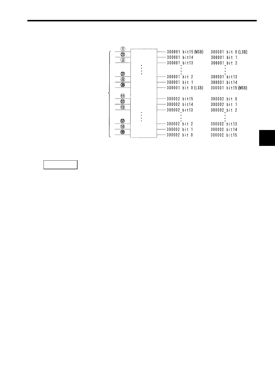
Fig. 3.4 Allocation of Input Registers
When allocating input registers, the MEMOSOFT is set by default to “LSB.”
When input register allocation is set to “LSB,” bit 15 (MSB) of the input register is
allocated to the smallest input number (input 1) on the Input Module.
b) Input Data Type
If an input register is set as the I/O reference number, data input can be set to binary
(BIN) or BCD. The MEMOSOFT is set by default to “BIN.”
c) Service Scan: Normal/High-speed
Two types of service scans are available: normal and high-speed. A service scan
is recommended when using the high-speed segment function. The I/O module is
activated before the ladder decoding of the high-speed segments. The I/Os that are
processed in synchronization with the high-speed scan are called High-speed Seg-
ment I/Os. The MEMOSOFT is set by default to “NORMAL.”
3.4.3
64-point Input Modules
1) Purpose of I/O Allocation
The relationship between I/O signals and I/O references must be defined so that the
CPU Module can input signals from input devices and output signals to output
devices. The following settings are necessary to define this relationship for Digital
Input Modules.
• Module Type
• I/O Reference Numbers
• I/O Data Format
Setting these items is performed in a process called I/O allocation. I/O allocation is
performed using the MEMOSOFT and the settings are recorded in the I/O allocation
tables stored in memory in the CPU Module.
Terminal number
Input signals
LSB Setting
MSB Setting
Input 1
Input 2
Input 3
Input 14
Input 15
Input 16
Input 17
Input 18
Input 19
Input 30
Input 31
Input 32
IMPORTANT