Caution – Yaskawa 120 Series I/O Modules User Manual
Page 87
3.2 Digital Output Module Specifications
3-57
3
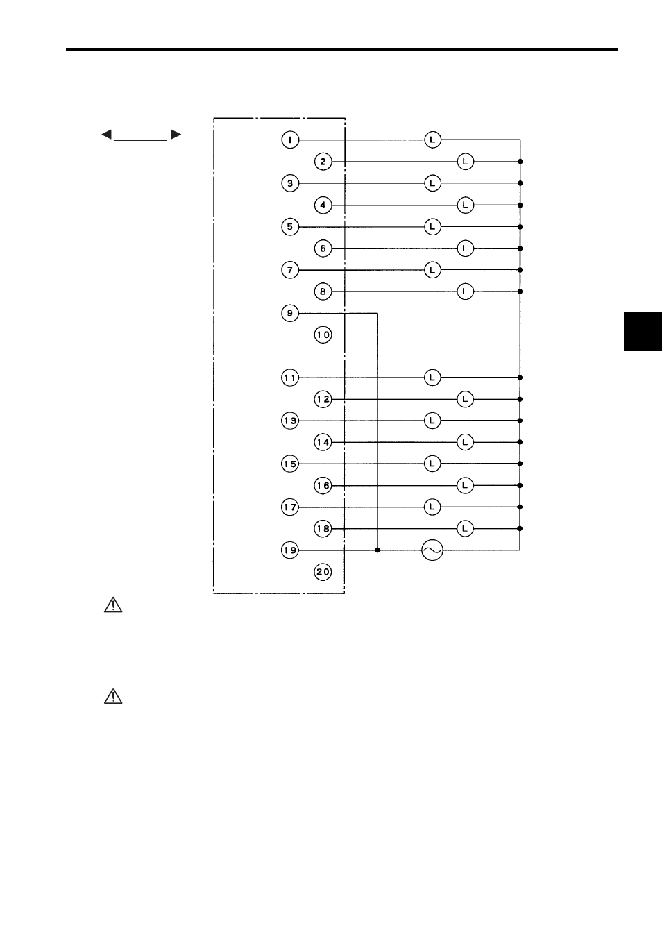
3) The following illustration shows an example of terminal connections with AC loads.
If using a single-phase 100/200-VAC power supply for driving loads of the Relay
Contact Output Module, connect a power supply of the same phase to the Common 1
and Common 2 of the Relay Contact Output Module.
If power supplies of different phases are connected, overheating or fire may
result.
If using a Relay Contact Output Module, connect a fuse, which complies with the load
specifications, in series with the load.
A protective fuse does not built into the following Relay Contact Output Mod-
ules. If a fuse is not connected, fire or damage to the devices or output circuits
may occur if the load is short-circuited or the circuit overloaded.
Note: (1) Crimp Terminals
Use M3 terminals for crimping to the terminal block.
(2) Recommended Wires
Use wires of 1.3 mm
2
(AWG16) to 0.5 mm
2
(AWG20) to connect to the terminal
block. Use cables of the size more than 1.3 mm
2
(AWG16) for common lines.
(3) Terminal 10 and terminal 20 are not connected.
Loads
Loads
Output 1
Output 2
Output 3
Output 4
Output 5
Output 6
Output 7
Output 8
Common 1
Not connected.
Output 9
Output 10
Output 11
Output 12
Output 13
Output 14
Output 15
Output 16
Common 2
Not connected.
100/200 VAC
Terminals
EXAMPLE
CAUTION
CAUTION