Yaskawa 120 Series I/O Modules User Manual
Page 97
3.3 I/O Module Cables
3-67
3
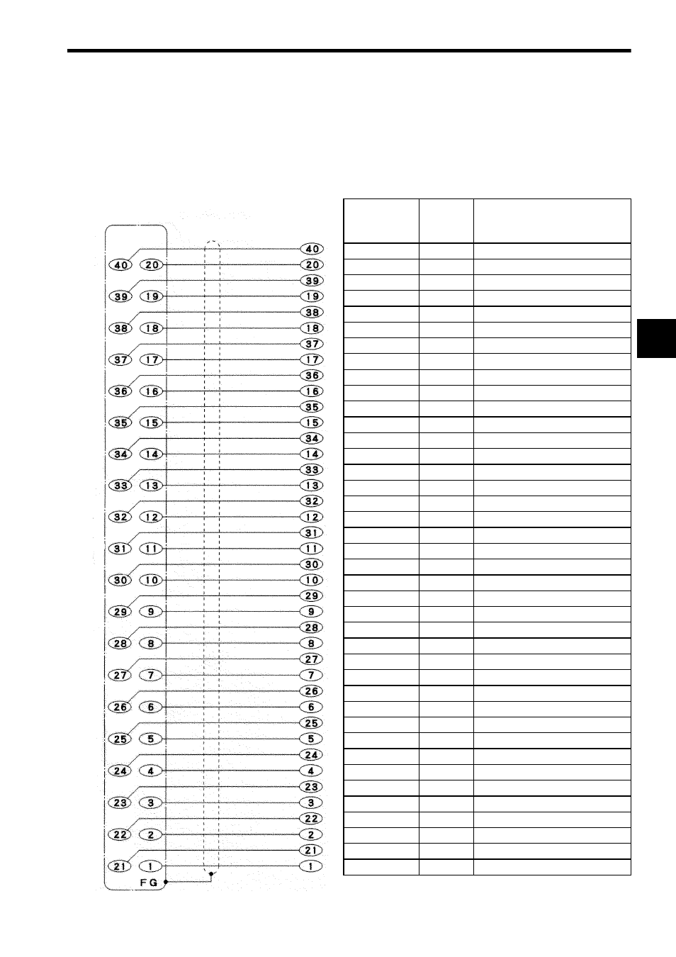
5) Connecting to External Output Device with Cable W0302
The following diagram shows signal names of wires when the W0302 Cable con-
nects the 12/24-VDC 32-point Output Module to an external output device. Connec-
tor pin numbers and dot marks are on each loose wire to identify the wire number
and its signal name.
Signal Name
Covering
Color
Dot Mark Dot:
Dash:
Space:
approx. 1 mm
approx. 3 mm
approx. 2 mm
+Common 2
Gray
+Common 2
Gray
− − − −
− − − −
-Common 2
Orange
-Common 2
Orange
− − − −
− − − −
Output 32
Green
Output 31
Green
− − − −
− − − −
Output 30
Pink
Output 29
Pink
− − − −
− − − −
Output 28
Light blue
Output 27
Light blue
− − − −
− − − −
Output 26
Gray
Output 25
Gray
− − −
− − −
Output 24
Orange
Output 23
Orange
− − −
− − −
Output 22
Green
Output 21
Green
− − −
− − −
Output 20
Pink
Output 19
Pink
− − −
− − −
Output 18
Light blue
Output 17
Light blue
− − −
− − −
+Common 1
Gray
+Common 1
Gray
− −
− −
-Common 1
Orange
-Common 1
Orange
− −
− −
Output 16
Green
Output 15
Green
− −
− −
Output 14
Pink
Output 13
Pink
− −
− −
Output 12
Light blue
Output 11
Light blue
− −
− −
Output 10
Gray
− − − − − − − − − − − − − − − −
Output 9
Gray
−
−
Output 8
Orange
− − − − − − − − − − − − − − − −
Output 7
Orange
−
−
Output 6
Green
− − − − − − − − − − − − − − − −
Output 5
Green
−
−
Output 4
Pink
− − − − − − − − − − − − − − − −
Output 3
Pink
−
−
Output 2
Light blue
− − − − − − − − − − − − − − − −
Output 1
Light blue
−
−
Connector on
the Module side
Pin No.
Shielded cable
Loose wire side
Wire No.