Yaskawa 120 Series I/O Modules User Manual
Page 269
6 Installation and Wiring
6.4.3 DC Input Modules
6-42
Fig. 6.23 Leakage Current from Input Devices (1)
The input voltage Vi input to the DC Input Module by a leakage current of 3 mA can
be calculated as follows:
This voltage will not go below 5 V as required by the OFF voltage range of the input
conditions, so the input signal will not go OFF.
Here, a dummy resistor can be connected in parallel with the input terminals of the
DC Input Module to correct the problem.
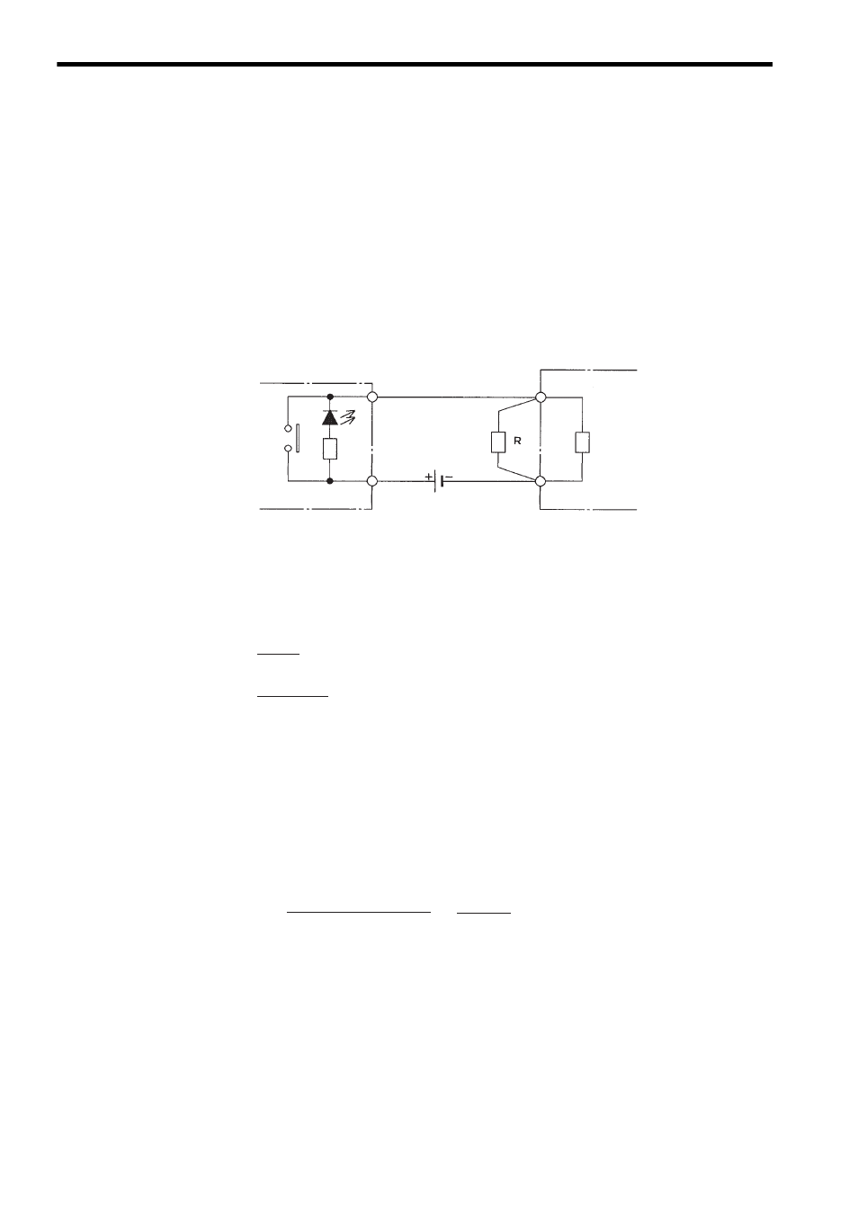
Fig. 6.24 Leakage Current from Input Devices (2)
The resistance of the dummy resistor must be selected so that the voltage Vi input
to the DC Input Module is 5 V or less.
Thus, the value for R should be 3.75 k
Ω or less.
If the resistance is too small, the amount of heat generation will increase, and a high
wattage will be required. Here, the wattage for a dummy resistor of 3 k
Ω is calcu-
lated.
The wattage of the dummy resistor is as follows:
Normally, about three times the computed value is used to allow surplus wattage.
A 0.5- to 1-W resistor would thus be used.
Vi = 3 mA
× Zi = 3 mA × 3.0 kΩ = 9.0 V
Input device
(limit switch with an LED)
DC Input Module
Input
Input impedance
Zi
Common
Power supply
for input signal
(12/24 VDC)
Dummy resistor
R
× Zi
R + Zi
× Leakage current < 5 V
R
× 3.0 kΩ
R + 3.0 k
Ω
× 3 mA < 5 V
∴
R < 3.75 k
Ω
W = = = Approx. 190 mW
(Power supply voltage)
R
2
(24 V)
3 k
Ω
2