Caution – Yaskawa 120 Series I/O Modules User Manual
Page 63
3.2 Digital Output Module Specifications
3-33
3
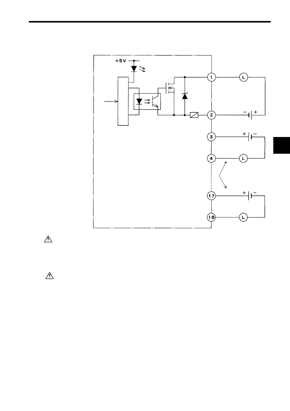
2) The following diagram shows the circuit configuration.
Do not replace the built-in fuses of the DC 8-point Output Modules.
If the built-in fuses are replaced by anyone other than a Yaskawa-approved
technician, a failure or malfunction may occur in the DC 8-point Output Mod-
ules, and the guarantee is void.
If using a 12/24-VDC 8-point Output Module, connect a fuse, which complies with the
load specifications, in series with the load.
A protective fuse built into the following 12/24-VDC 8-point Output Modules
does not protect the output element. If a fuse is not connected, a fire or dam-
age to the devices or output circuits may occur if the load is short-circuited or
the circuit overloaded.
Note: A blown-fuse detection circuit is not built into the circuit. If no output current flows
while the output signal indicator is lit under the rated voltage, the built-in fuse may
be blown. The built-in fuse must be replaced by a Yaskawa service representative.
Output 1A
12/24 VDC
12/24 VDC
Output signal
indicator
From CPU
Photocoupler
Loads
Loads
Fuse
Loads
12/24 VDC
Output 1B
Output 2A
Output 2B
Output 8A
Output 8B
Sourcing connection
Sinking connection
Internal circuits
CAUTION
CAUTION