4) leakage current from input devices – Yaskawa 120 Series I/O Modules User Manual
Page 261
6 Installation and Wiring
6.4.1 AC Input Modules
6-34
4) Leakage Current from Input Devices
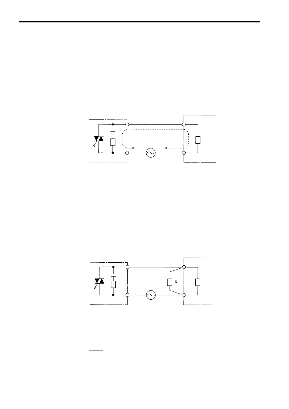
When connecting an input device that exhibits leakage current during the OFF state
(such as non-contact switches or limit switches with neon lamps) to an AC Input
Module, the leakage current may be too large to stay within the OFF voltage range
and the input signal may never go OFF.
The following diagram shows what can happen when a non-contact switch with a 5-
mA leakage current is connected to the AC Input Module (100 VAC).
Fig. 6.11 Leakage Current from Input Devices
The input voltage Vi Input to the AC Input Module by a leakage current of 5 mA can
be calculated as follows:
This voltage will not go below 30 V as required by the OFF voltage range of the
input conditions, so the input signal will not go OFF.
Here, a dummy resistor can be connected in parallel with the input teminals of the
AC Input Module to correct the problem.
Fig. 6.12 Connecting a Dummy Resistor
The resistance of the dummy resistor must be selected so that the voltage Vi input
to the AC Input Module is 30 V or less.
Therefore, the resistance of the dummy resistor must be 10.3 k
Ω or less.
Input device
(non-contact switch)
AC Input Module
Input
Common
Input impedance
Zi
Power supply
for input signals
(74 to 132 VAC)
Leakage current = 5 mA
Vi = 5 mA
× Zi = 5 mA × 14.3 k = 72 V
Input device
(non-contact switch)
AC Input Module
Input
Common
Input impedance
Zi
Power supply
for input signal
(74 to 132 VAC)
Dummy resistor
R
× Zi
R + Zi
× Leakage current < 30 V
R
× 14.3 kΩ
R + 14.3 k
Ω
× 5 mA < 30 V
∴
R < 10.3 k
Ω