4) i/o data format – Yaskawa 120 Series I/O Modules User Manual
Page 132
3 Digital I/O Specifications
3.4.7 64-point Output Modules
3-102
(c) When an output coil is set, the leading I/O reference number must satisfy the
following equation:
Leading reference number of I/O coil = 000001 + 16 n
where n = 0 to 63 for the CPU20 and
n = 0 to 255 for the CPU30
For example, 000001 can be set as the leading reference number, but
000002 cannot.
4) I/O Data Format
The following items can be set to define the I/O data format. There is, however, gen-
erally no need to change these settings because the default settings can be used
for most normal applications.
a) Bit Order
I/O can be processed by handling data either in ascending or descending order of
the bits. This is explained next for allocation of both output coils and output regis-
ters.
(1) When 64-point output coils are allocated from 000001, the bit order can be set
to either “MSB” or “LSB,” as described in the following table and shown in the
illustration below it. Allocation is performed in units of 16 input points.
Refer to Fig 2.13 Allocation of Output Coils for details.
(2) When four output registers are allocated from 400001, the bit order can be set
to either “MSB” or “LSB,” as described in the following table and shown in the
illustration below it. Allocation is performed in units of 16 input points.
Refer to Fig. 3.14 Allocation of Output Registers for details.
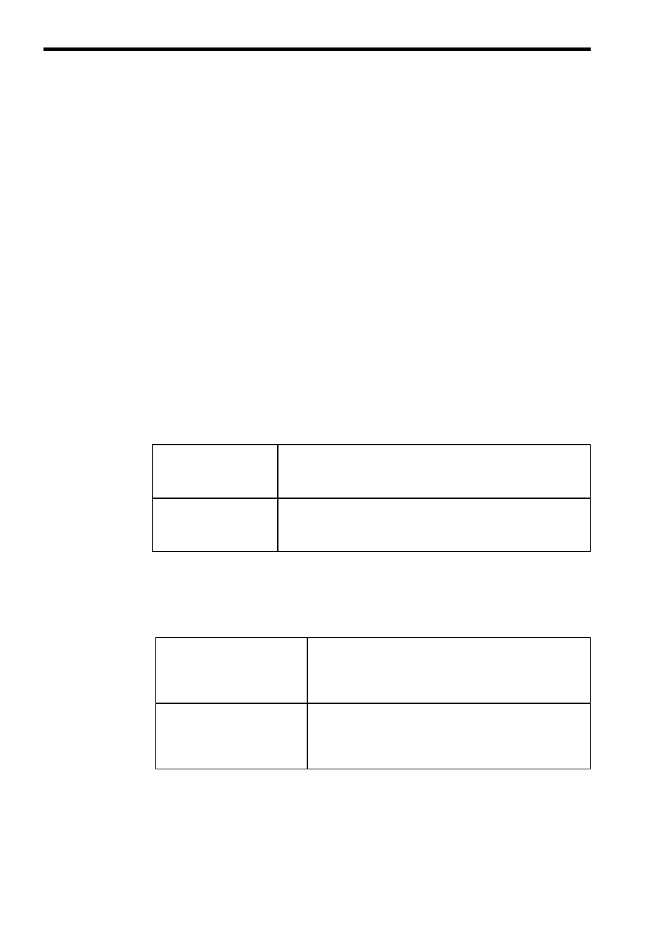
Output Coil MSB Setting
The leading output reference number (000001) is allocated to the
smallest output number (output 1) of the first 16 points on the Output
Module, and then the next output reference number (000017) is allo-
cated to the smallest output number (output 17) of the next 16 points.
Output Coil LSB Setting
The leading output reference number (000001) is allocated to the
largest output number (output 16) of the first 16 points on the Output
Module, and then the next output reference number (000017) is allo-
cated to the largest output number (output 32) of the next 16 points.
Output Register LSB Setting
Bit 15 (MSB) of the leading output register (400001) is allo-
cated to the smallest output number (output 1) of the first 16
points on the Output Module, and then the bit 15 (MSB) of the
next output register (400002) is allocated to the smallest out-
put number (output 17) of the next 16 points.
Output Register MSB Setting
Bit 15 (MSB) of the leading output register (400001) is allo-
cated to the largest output number (output 16) on the Output
Module, and then the bit 15 (MSB) of the next output register
(400002) is allocated to the largest input number (output 32) of
the next 16 points.