Warning, Caution – Yaskawa 120 Series I/O Modules User Manual
Page 17
1 Introduction and Precautions
1.2.5 Application Precautions
1-12
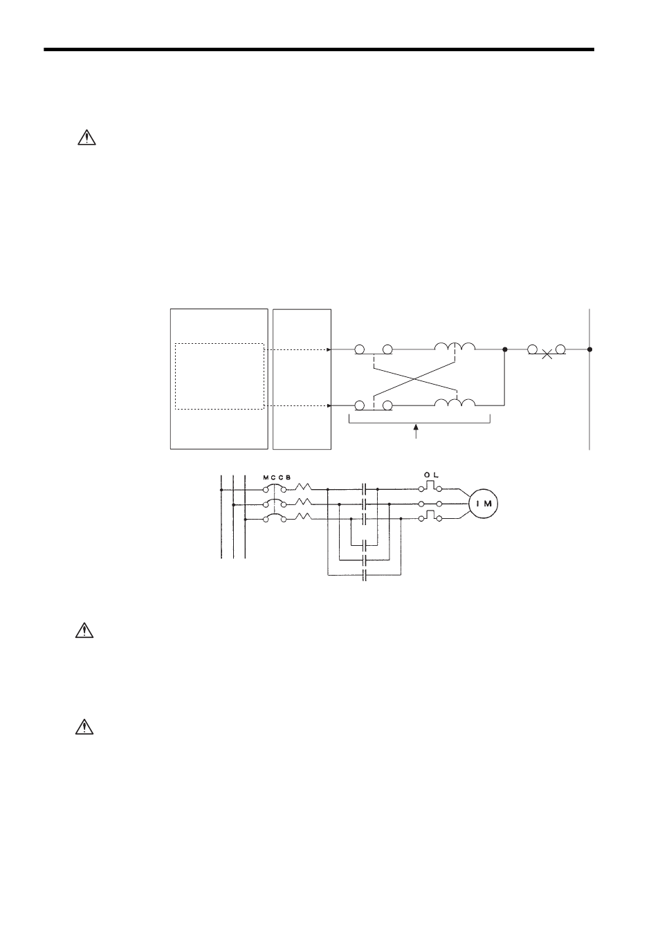
External Interlocks for the GL120 and GL130
Externally connect an interlock to the GL120 and GL130 if there is any chance
that GL120 and GL130 failure could result in bodily harm or equipment damage.
Always use an external interlock system as shown in the following example
when reciprocal operations (e.g., forward and reverse directions) are being per-
formed with a motor.
An interlock is generally programmed in the GL120 and GL130 ladder program
to ensure that forward and reverse signals are not simultaneously output. An
external interlock circuit must also be provided using the auxiliary contacts of
electromagnetic contactors.
• When inserting or removing an AC I/O Module while the AC power supply is turned
ON, install a safety switch for each Module and always turn this safety switch OFF
to turn OFF the AC power supply to the Module.
Inserting or removing an AC I/O Module while AC power is being supplied may
result in an electric shock at touching the power supply terminals.
• When using a single-phase AC power supply (100/200 VAC) for driving the loads of
the Relay Contact Output Module, install a safety switch for each Module. Before
inserting or removing the Relay Contact Output Module, always turn this safety
switch OFF to turn OFF the AC power supply to the Module.
Inserting or removing a Relay Contact Output Module while AC power is being
supplied may result in an electric shock at touching the power supply terminals.
WARNING
R (Reverse run)
F (Forward run)
Induction motor
R
R
F
F
OL
CPU Module
Output Module
Ladder logic program
Output program with
an interlock which
prohibit simultaneous
forward and reverse
runs
Contact of over-
current protection
device.
Electric interlock using the auxiliary contacts
of electromagnetic contactors
CAUTION
CAUTION