Yaskawa 120 Series I/O Modules User Manual
Page 93
3.3 I/O Module Cables
3-63
3
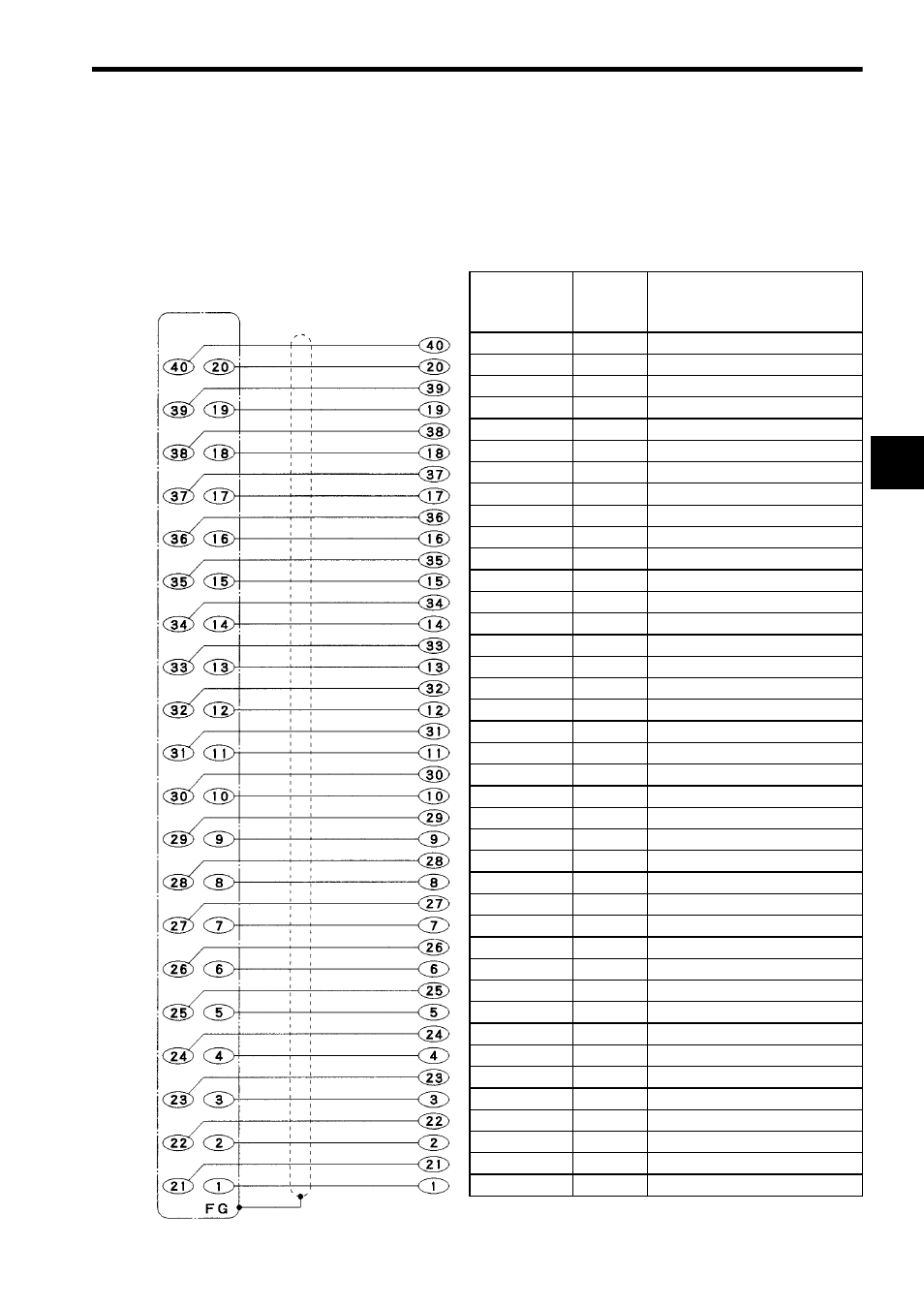
4) Connecting to External Input Device with Cable W0300
The following diagram shows signal names of wires when the W0300 Cable con-
nects the 12/24-VDC 32-point Input Module to an external input device. Connector
pin numbers and dot marks are on each loose wire to identify the wire number and
its signal name.
Signal Name
Covering
Color
Dot Mark Dot:
Dash:
Space:
approx. 1 mm
approx. 3 mm
approx. 2 mm
Not connected Pink
Not connected Pink
− − − −
− − − −
Common 2
Yellow
Common 2
Yellow
− − − −
− − − −
Input 32
White
Input 31
White
− − − −
− − − −
Input 30
Light gray
Input 29
Light gray
− − − −
− − − −
Input 28
Orange
Input 27
Orange
− − − −
− − − −
Input 26
Pink
Input 25
Pink
− − − −
− − − −
Input 24
Yellow
Input 23
Yellow
− − −
− − −
Input 22
White
Input 21
White
− − −
− − −
Input 20
Light gray
Input 19
Light gray
− − −
− − −
Input 18
Orange
Input 17
Orange
− − −
− − −
Not connected Pink
Not connected Pink
− −
− −
Common 1
Yellow
Common 1
Yellow
− −
− −
Input 16
White
Input 15
White
− −
− −
Input 14
Light gray
Input 13
Light gray
− −
− −
Input 12
Orange
Input 11
Orange
− −
− −
Input 10
Pink
− − − − − − − − − − − − − − − −
Input 9
Pink
−
−
Input 8
Yellow
− − − − − − − − − − − − − − − −
Input 7
Yellow
−
−
Input 6
White
− − − − − − − − − − − − − − − −
Input 5
White
−
−
Input 4
Light gray
− − − − − − − − − − − − − − − −
Input 3
Light gray
−
−
Input 2
Orange
− − − − − − − − − − − − − − − −
Input 1
Orange
−
−
Connector on
the Module side
Pin No.
Shielded cable
Loose wire side
Wire No.