6 connections between dc i/o modules, 7 analog input modules, 1) input circuit insulation – Yaskawa 120 Series I/O Modules User Manual
Page 277: 2) analog input signal wires, Caution
6 Installation and Wiring
6.4.6 Connections between DC I/O Modules
6-50
6.4.6
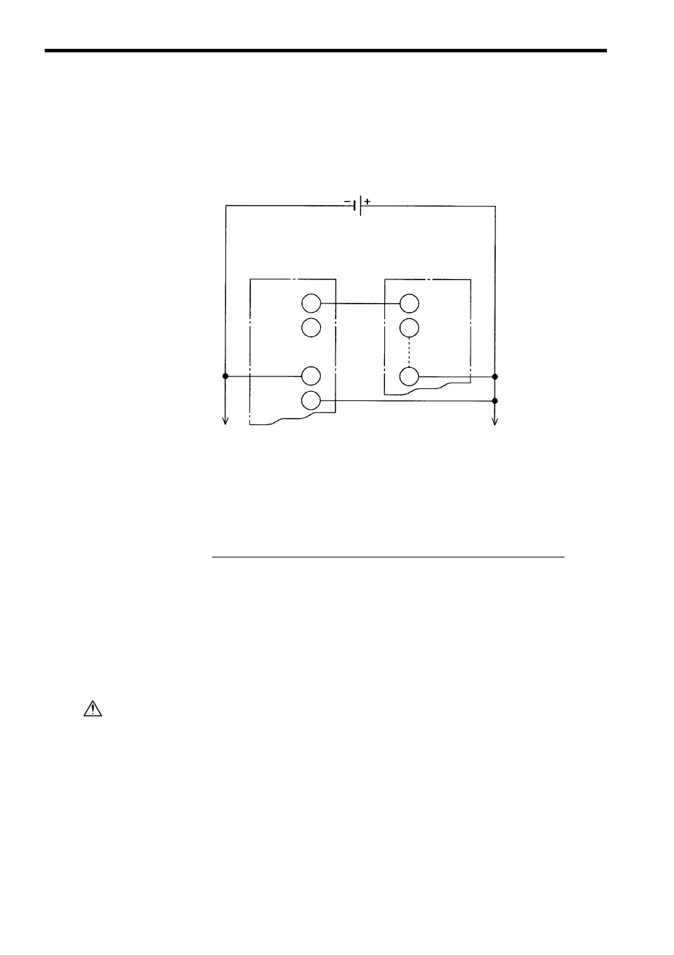
Connections between DC I/O Modules
1) Whenever two or more GL120 or GL130 PLCs are used in a system, connect them as
shown in the following figure to exchange signals between the DC I/O Modules of the
GL120 or GL130.
Fig. 6.32 Connections between DC I/O Modules
2) Using GL120 or GL130 in Combination with Existing MEMOCON PLCs
When signals are exchanged between existing MEMOCON PLCs and a GL120 or
GL130 PLC through a DC Input Module and a DC Output Module, the following items
must be considered. Contact your Yaskawa representative.
6.4.7
Analog Input Modules
1) Input Circuit Insulation
Insulation is not provided between the channels of the Analog Input Module.
To insulate all the analog signals connected to the Analog Input Module, use a
commercial isolation amplifier for each channel.
Incorrect connections may cause damages and malfunctions of the Analog
Input Modules.
2) Analog Input Signal Wires
Use Shielded twisted-pair wires for the analog input signal lines. An improper con-
nection will cause noise interference, which results in a malfunction.
DC Output Module
DC Input Module
Output
-Common
+Common
Input
Input
Common
12 VDC
(24 VDC)
Output
DC Output Module
DC Input Module
1
Rated Voltage
Rated Voltage
2
Output Type (Source or Sink)
Input Type (Source or Sink)
3
Maximum Load Current
>
Rated Current
4
Output Voltage Drop
<
Maximum OFF Voltage Range
CAUTION