Yaskawa 120 Series I/O Modules User Manual
Page 129
3.4 I/O Allocation
3-99
3
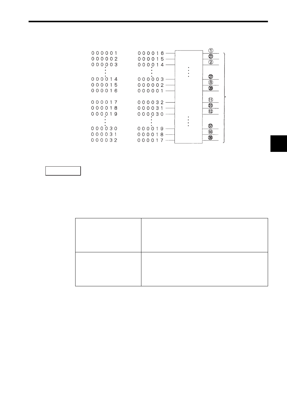
Fig. 3.11 Allocation of Output Coils
When allocating output coils, the MEMOSOFT is set by default to “MSB.”
When output coil allocation is set to “MSB,” the leading reference number is allocated
to the smallest output number (output 1) on the Output Module.
(2) When two output registers beginning with output register 400001 are allocated,
the bit order can be set to either “MSB” or “LSB,” as described in the following
table and shown in the illustration below it. Allocation is performed in units of 16
output points.
Refer to Fig. 3.12 Allocation of Output Registers for details.
Terminal number
Output signals
MSB Setting
LSB Setting
Output 1
Output 2
Output 3
Output 14
Output 15
Output 16
Output 17
Output 18
Output 19
Output 30
Output 31
Output 32
IMPORTANT
Output Register LSB Setting
Bit 15 (MSB) of the leading output reference number (400001) is
allocated to the smallest output number of the first 16 output
points (output 1) on the Output Module. Bit 15 (MSB) of the sec-
ond output reference number (400002) is allocated to the small-
est output number of the second 16 output points (output 17) on
the Output Module.
Output Register MSB Setting
Bit 15 (MSB) of the leading output reference number (400001) is
allocated to the largest output number of the first 16 output
points (output 16) on the Output Module. Bit 15 (MSB) of the
second output reference number (400002) is allocated to the
largest output number of the second 16 output points (output 32)
on the Output Module.