Caution – Yaskawa 120 Series I/O Modules User Manual
Page 68
3 Digital I/O Specifications
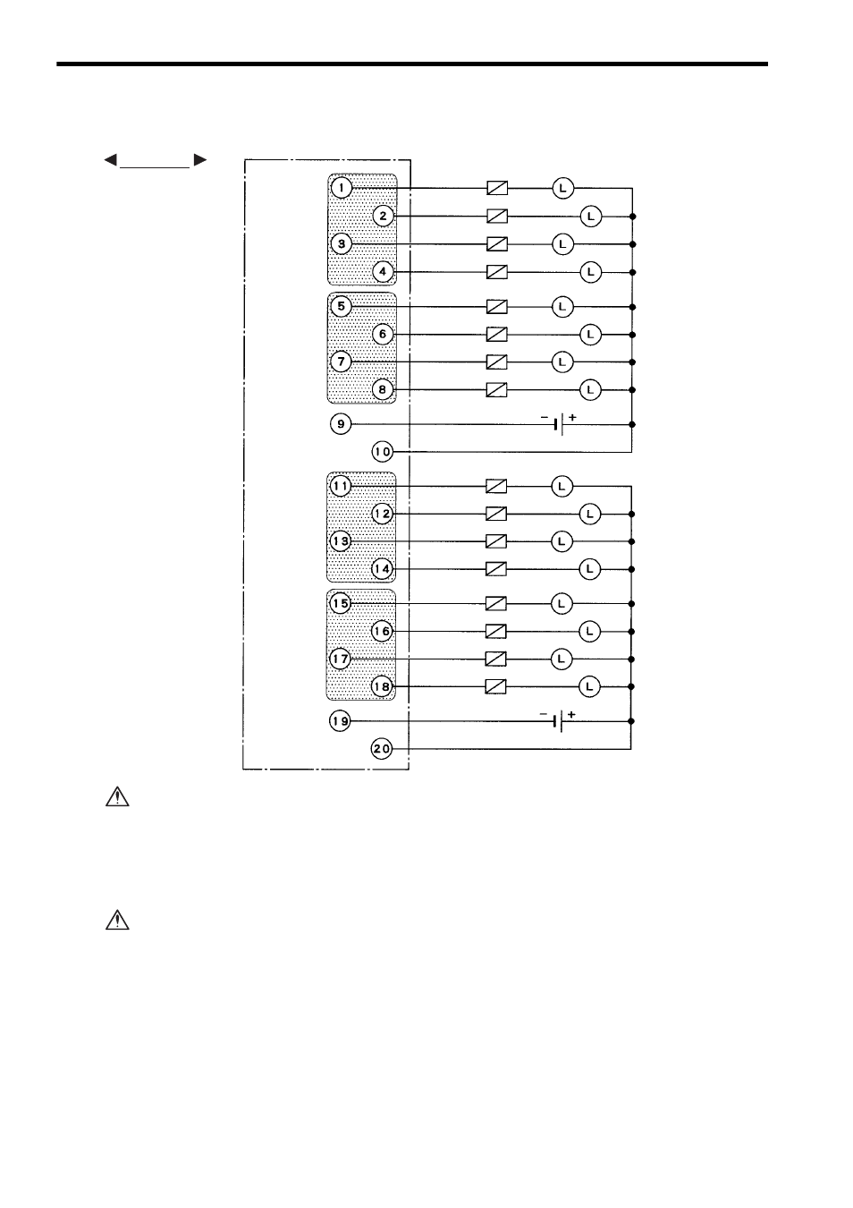
3.2.4 12/24-VDC 16-point Output Module (Sinking)
3-38
3) The following diagram shows an example of terminal connections.
Although a 0.5 A load can be connected to each output point of the 12/24-VDC 16-
point Output Module (sinking), the total load must be 1.0A or less for each of the four
output points shown in the shaded areas. Keep the load distribution within the 1.0A
limit.
It this limit is exceeded, damage may occur to the output circuit.
If using a 12/24-VDC 16-point Output Module (sinking), connect a fuse, which
complies with the load specifications, in series with the load.
A protective fuse built into the following 12/24-VDC 16-point Output Modules
does not protect the output element. If a fuse is not connected, a fire or dam-
age to the devices or output circuits may occur if the load is short-circuited or
the circuit overloaded.
Note: (1) Crimp Terminals
Use M3 terminals for crimping to the terminal block.
(2) Recommended Wires
Use wires of 0.8mm
2
(AWG18) to 0.2mm
2
(AWG24) to connect to the terminal
block.
Output 1
Output 2
Output 3
Output 4
Output 5
Output 6
Output 7
Output 8
- Common 1
+ Common 1
Output 9
Output 10
Output 11
Output 12
Output 13
Output 14
Output 15
Output 16
- Common 2
+ Common 2
Loads
Loads
Fuse
Fuse
12/24 VDC
12/24 VDC
Terminals
EXAMPLE
CAUTION
CAUTION