Yaskawa 120 Series I/O Modules User Manual
Page 99
3.3 I/O Module Cables
3-69
3
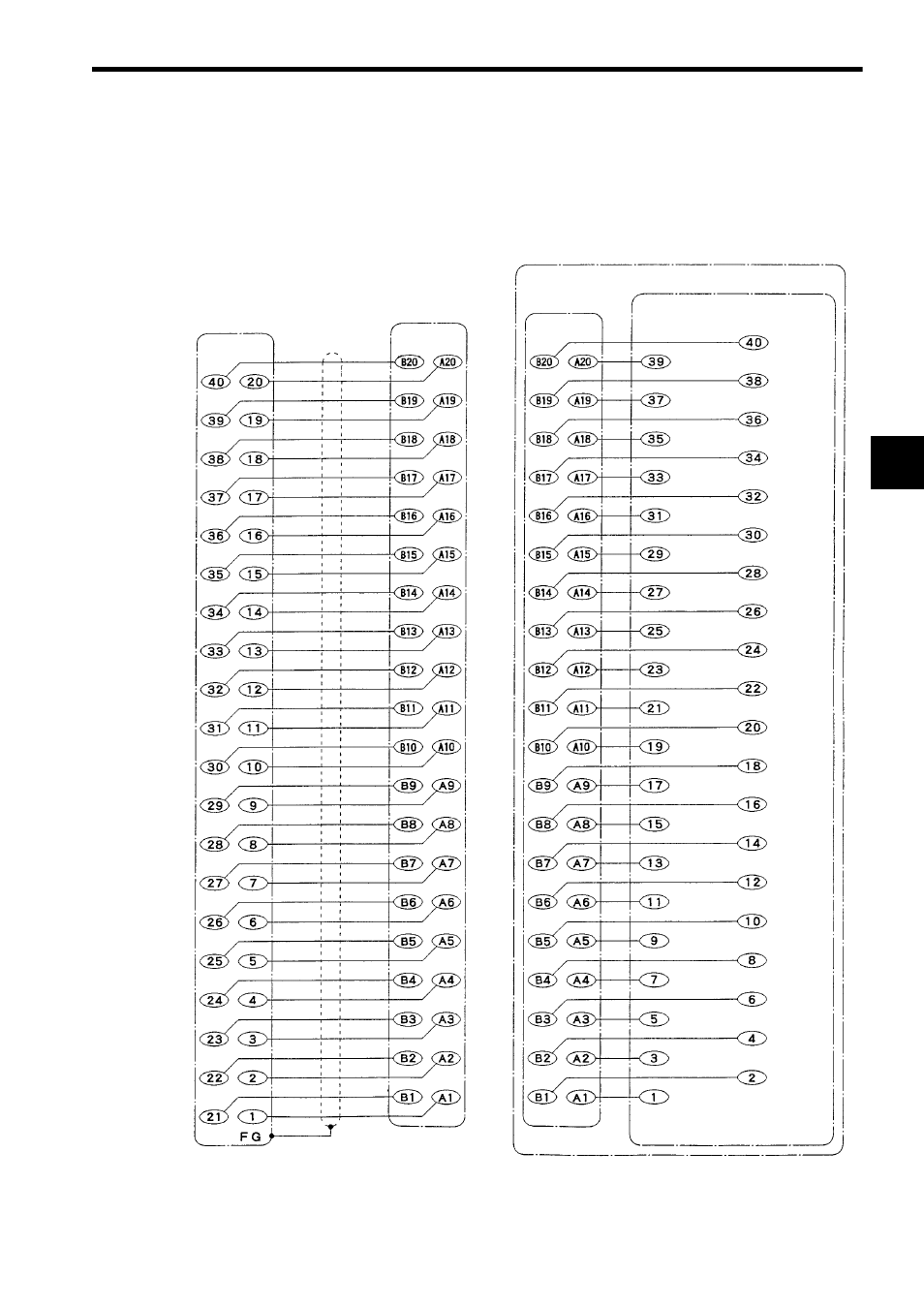
4) Connecting to External Input Device with Cable W0301
The following diagram shows the signal names of terminals when the W0301 Cable
and 32-point terminal I/O terminal connector block are used to connect the 12/24
VDC 32-point Input Module to an external input device.
32-point I/O Module Cable (W0301)
Connector on
the Module side
Pin No.
Shielded cable
Connector on the
terminal block side
Connector
Terminal block
Signal name
Signal name
Not con-
nected
32-point I/O Connector Terminal Block (XW2B-40F5-P)
Pin No.
Not connected
Common 2
Input 31
Input 29
Input 27
Input 25
Input 23
Input 21
Input 19
Input 17
Input 15
Input 13
Input 11
Input 9
Not connected
Common 1
Input 7
Input 5
Input 3
Input 1
Common 2
Not con-
nected
Common 1
Input 32
Input 30
Input 28
Input 26
Input 24
Input 22
Input 20
Input 18
Input 16
Input 14
Input 12
Input 10
Input 8
Input 6
Input 4
Input 2
Pin No.