8 encoder signal converter unit, 1) model: lrx-01 / a, 2) specifications (3) dimensional drawings – Yaskawa Sigma II Series DC Power Input SGMAJ User Manual
Page 119
5 Specifications and Dimensional Drawings of Cables and Peripheral Devices
5.6.8 Encoder Signal Converter Unit
5-22
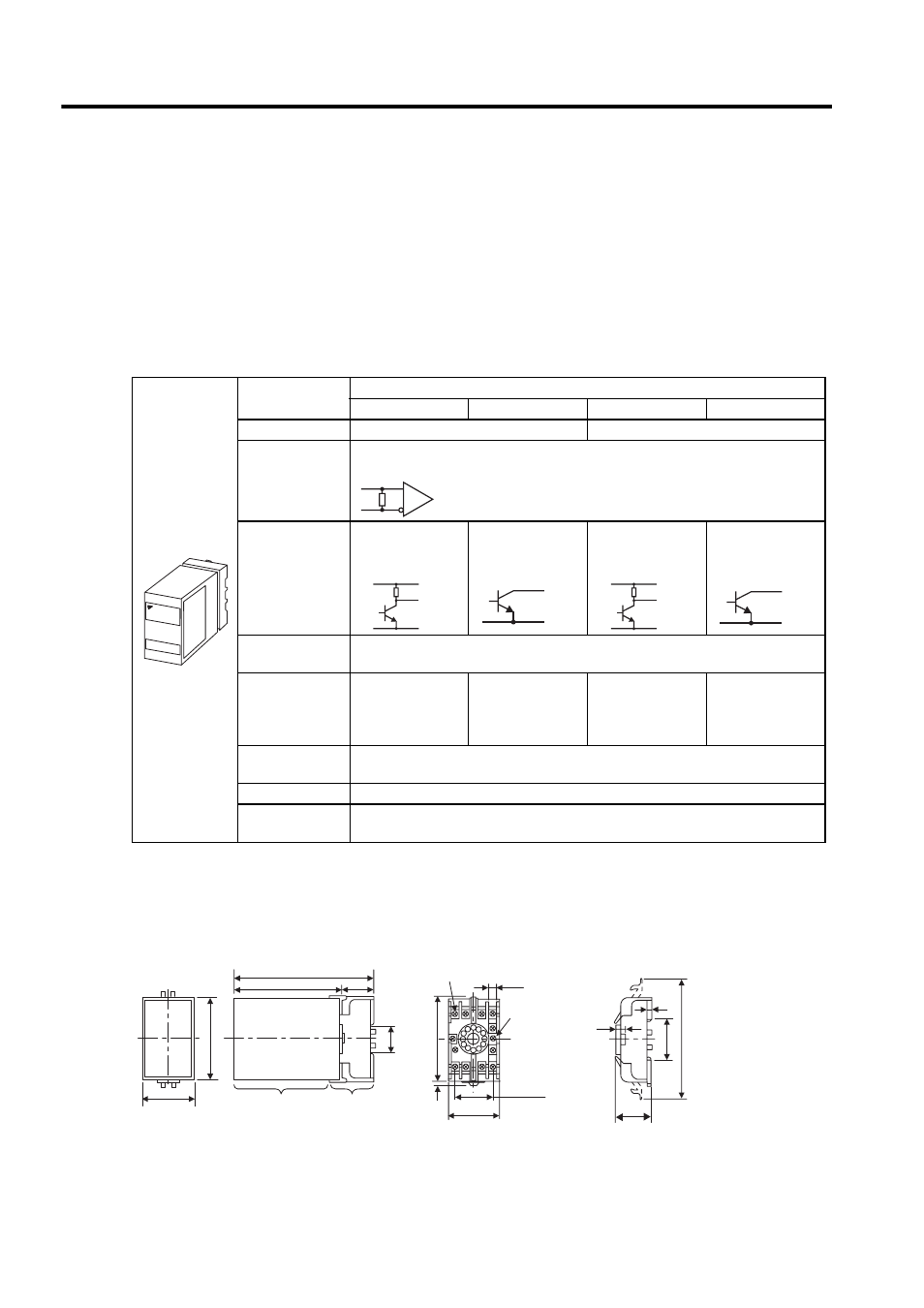
5.6.8 Encoder Signal Converter Unit
The encoder signal converter unit (the trade name “Receiver Unit”) converts encoder signal output from the line
driver to open-collector or voltage-pulse output.
A socket model 11PFA is required to use a Receiver Unit.
(1) Model: LRX-01 / A
Contact Yaskawa Controls Co., Ltd.
(2) Specifications
(3) Dimensional Drawings
The socket is optional.
Specifications
Receiver Unit
LRX-01/A1
LRX-01/A2
LRX-01/A3
LRX-01/A4
Power Supply
12 VDC
±10 %, 100 mA
5 VDC
±5 %, 100 mA
Input Signals
Balanced line driver input (RS-422)
Output Signals
Voltage pulse out-
put
Open collector
output
Voltage pulse out-
put
Open collector
output
Input Signal
Level
Differential voltage
≥ 0.3 V, built-in terminator 100 Ω
Output Signal
Level
H: 10 V min.
(1 mA)
L: 0.5 V max.
(30 mA)
L: 0.5 V max.
(30 mA)
Withstand volt-
age: 50 V
H: 3 V min.
(1 mA)
L: 0.5 V max.
(30 mA)
L: 0.5 V max.
(30 mA)
Withstand volt-
age: 50 V
Ambient
Temperature
0 (32
°F) to + 60 °C (140 °F)
IC Used
Receiver IC: AM26LS32C or the equivalent
Response
Frequency
100 kHz
YASKAWA
RS-422
Input Circuit
Output Circuit
Output Circuit
Output Circuit
Output Circuit
5 (0.20)
33.5 (1.32) max.
18 (4.65 max.)
35.4 (1.39)
4
(0.16)
4
(0.16)
7.8 (0.31)
11-M3.5
×7
SEMS screws
51 (2.01) max.
40
±0.2
(1.57
±0.0079)
81 (3.19) max.
2
φ4.5
(
φ0.18) hole
50 (1.97)
80 (3.15)
35.4 (1.39)
129 (5.08)
100 (3.94)
Socket
Receiver unit
29
(1.14)
Receiver unit and socket
Socket Type 11PFA
Units: mm (in)