3 position reference, 1) input/output signal timing example, Important – Yaskawa Sigma II Series DC Power Input SGMAJ User Manual
Page 225
8 Operation
8.6.3 Position Reference
8-52
8.6.3 Position Reference
The servomotor positioning is controlled by inputting a pulse train reference.
The pulse train output form from the host controller corresponds to the following:
• Line-driver Output
• +24V Open-collector output
• +12V Open-collector output
• +5V Open-collector output
Precautions for Open-collector Output
When the open-collector output is used, input signal noise margin lowers. Change the parameter as follows:
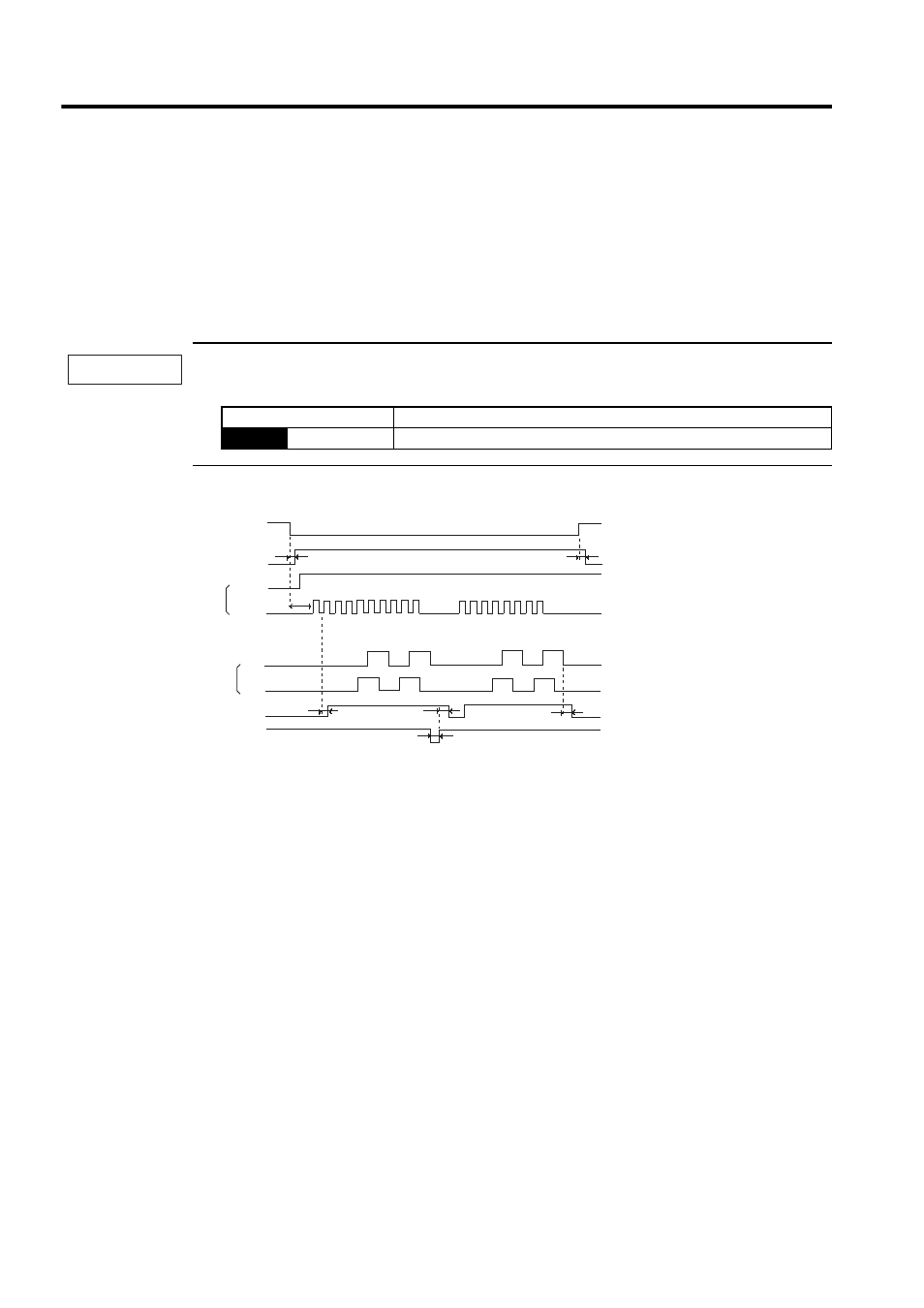
(1) Input/Output Signal Timing Example
Note: 1. The interval from the time the servo ON signal is turned ON until a reference pulse is input must
be at least 40 ms, otherwise the reference pulse may not be received by the SERVOPACK.
2. The error counter clear signal must be ON for at least 20
µ
s.
Parameter
Description
Pn200
n.1
Reference input filter for open-collector signal
IMPORTANT
Servo ON
Baseblock
Sign + pulse train
Release
t1
≤ 30 ms
t2
≤ 6 ms
(When parameter Pn506 is set to 0.)
t3
≥ 40 ms
Encoder pulses
t4, t5, t6
≤ 2 ms
t7
≥ 20 µs
t6
CN1-11
CN1-7
PAO
L
L
L
H
H
H
H
ON
ON
ON
CLR
PBO
t7
t5
t4
t3
t2
t1
/COIN