2) output signals – Yaskawa Sigma II Series DC Power Input SGMAJ User Manual
Page 132
6.3 Examples of I/O Signal Connections
6-13
6
Note: 1. Pin numbers in parentheses () indicate signal grounds.
2. The functions allocated to /S-ON, /P-CON. P-OT, N-OT, /ALM-RST, /P-CL, and /N-CL input
signals can be changed by using the parameters. Refer to 7.3.2 Input Circuit Signal Allocation.
3. The voltage input range for speed and torque references is a maximum of
±12 V.
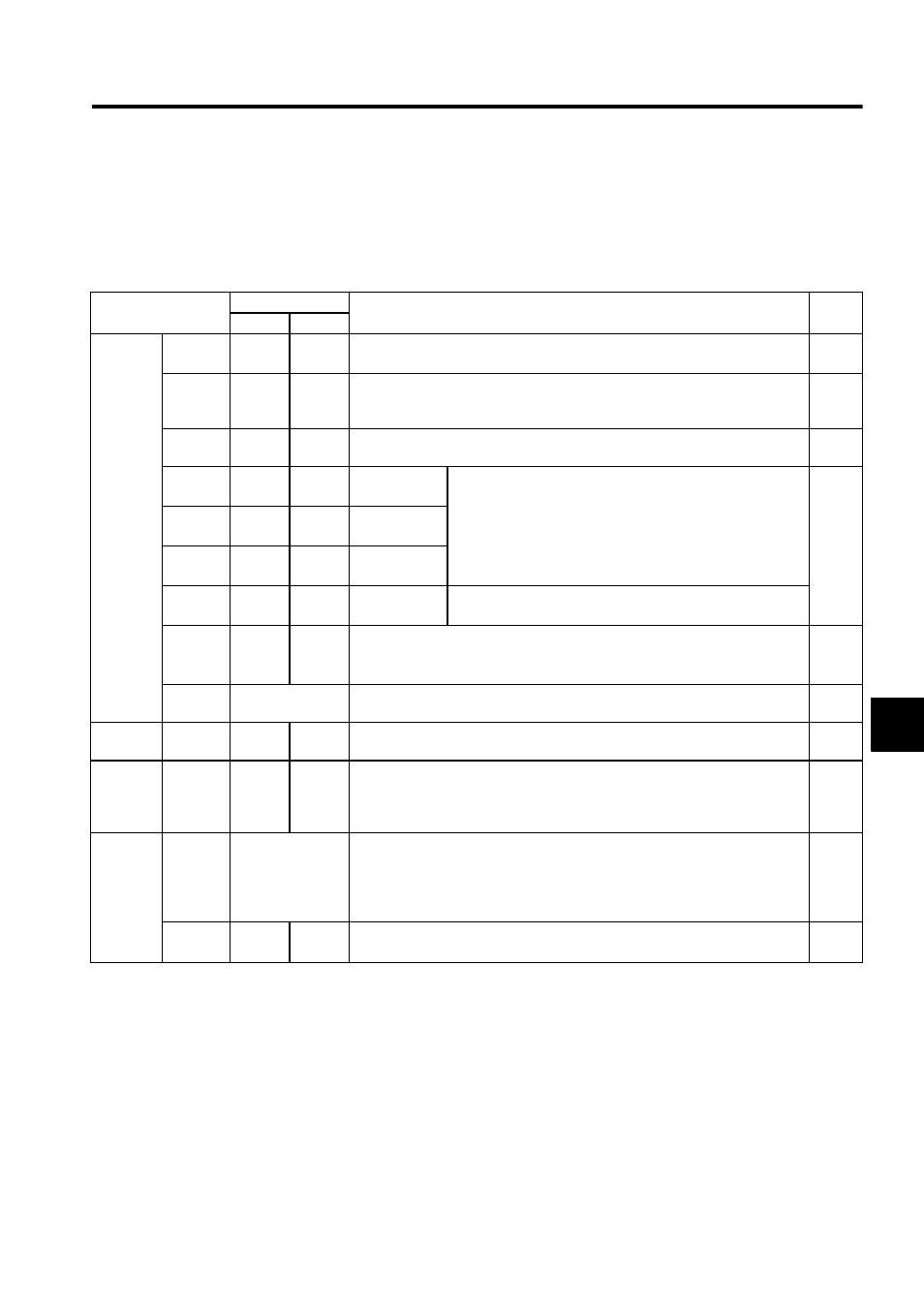
(2) Output Signals
Note: 1. Pin numbers in parentheses () indicate signal grounds.
2. The functions allocated to /TGON, /S-RDY, and /V-CMP (/COIN) can be changed by using the
parameters. /CLT, /VLT, /BK, /WARN, and /NEAR signals can also be changed. Refer to 7.3.3
Output Circuit Signal Allocation.
Signal Name
SGDJ-
Function
Refer-
ence
S P
Common
ALM+
ALM-
34
35
34
35
Servo alarm: Turns OFF when an error is detected.
8.11.1
/TGON
9 (10)
9 (10)
Detection during servomotor rotation: Detects when the servomotor is rotating
at a speed higher than the motor speed setting. Detection speed can be set by
using the parameters.
8.11.3
/S-RDY
7 (10)
7 (10)
Servo ready: ON if there is no servo alarm when the control/main circuit power
supply is turned ON.
8.11.4
PAO
/PAO
21
22
21
22
Phase-A signal Converted two-phase pulse (phases A and B) encoder output
signal and zero-point pulse (phase C) signal: RS-422 or the
equivalent
(Proper line receiver is SN75175 manufactured by Texas
Instruments or the equivalent corresponding to MC3486.)
6.2
6.3.1
8.4.6
8.5.7
PBO
/PBO
23
24
23
24
Phase-B signal
PCO
/PCO
25
26
25
26
Phase-C signal
PSO
/PSO
27
28
27
28
Phase-S signal
With an absolute encoder: Outputs serial data corresponding
to the number of revolutions (RS-422 or the equivalent)
ALO1
ALO2
ALO3
30
31
32 (33)
30
31
32 (33)
Alarm code output: Outputs 3-bit alarm codes.
Open-collector: 30 V and 20 mA rating maximum
8.11.1
FG
Shell
Connected to frame ground if the shield wire of the I/O signal cable is connected
to the connector shell.
−
Speed
/V-CMP
8 (10)
−
Speed coincidence (output in Speed Control Mode): Detects whether the motor
speed is within the setting range and if it matches the reference speed value.
8.5.8
Position
/COIN
−
8 (10)
Positioning completed (output in Position Control Mode): Turns ON when the
number of positional error pulses reaches the value set. The setting is the num-
ber of positional error pulses set in reference units (input pulse units defined by
the electronic gear).
8.6.5
Reserved
/CLT
/VLT
/BK
/WARN
/NEAR
−
Reserved terminals
The functions allocated to /TGON, /S-RDY, and /V-CMP (/COIN) can be
changed by using the parameters.
8.3.4
8.6.6
8.7.4
8.9.5
8.11.2
−
36
−
Terminals not used
Do not connect relays to these terminals.
−