2 encoder connector (cn2) terminal layout, 6 (2) absolute encoders – Yaskawa Sigma II Series DC Power Input SGMAJ User Manual
Page 125
6 Wiring
6.2.2 Encoder Connector (CN2) Terminal Layout
6-6
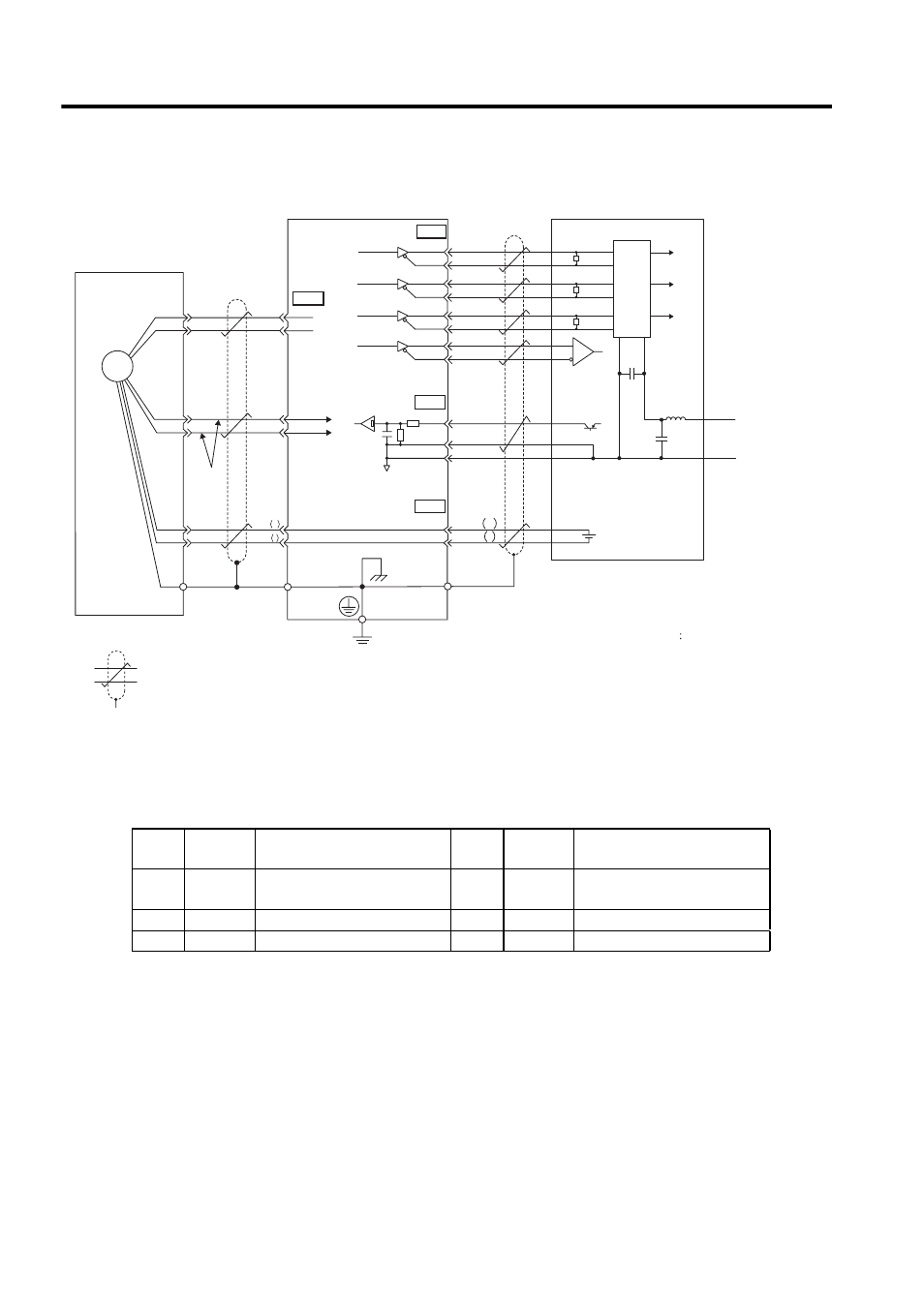
(2) Absolute Encoders
6.2.2 Encoder Connector (CN2) Terminal Layout
Absolute encoder
SERVOPACK
: represents twisted-pair wires.
The pin numbers for the SEN signal differ depending on the SERVOPACK models.
SGDJ-S: CN1-5
SGDJ-P: CN1-36
∗2
∗1
Line receiver
Host controller
/PCO
PG
3
4
5 (36)
*2
6 (19) SG
SEN
28
29
BAT
BAT
+
-
CN4
20
21
22
23
24
25
26
27
CN1
0 V
SG
PG5 V
PG0 V
PAO
/PAO
PBO
/PBO
PCO
/PSO
PSO
0.33 mm
2
CN1
CN1
∗1
∗1
0 V
0 V
+5 V
+5 V
+5 V
11
5
3
2
1
R
6
7
10
9
8
16
C
+
-
R
R
+
-
5
6
1
2
PG5V
PG0V
PS
/PS
BAT +
BAT -
5
6
1
2
3
4
Shield wire
Orange
White/Orange
(Shell)
Connector
shell
Connector
shell
Applicable line receiver: SN75175 manufactured
by Texas Instruments or the
equivalent corresponding to MC3486.
R (terminator): 220 to 470
Ω
C (Decoupling Capacitor) 0.1
µF
Battery
Phase A
Phase B
Phase C
Phase
A
Phase
B
Phase
C
Phase S
Choke
coil
Smoothing
capacitor
(0.001in
2
)
J
Light
blue
White/Light blue
Red
Black
Output line-driver SN75ALS194
manufactured by Texas
Instruments or the equivalent.
1
PG5V
PG power supply
+5 V
2
PG 0 V
PG power supply
0 V
3
BAT (+)
Battery (+)
(For an absolute encoder)
4
BAT (-)
Battery (-)
(For an absolute encoder)
5
PS
PG serial signal input
6
/PS
PG serial signal input
SHELL Shield
−
−
−
−