5 checking output torque limiting during operation, 2) input signals – Yaskawa Sigma II Series DC Power Input SGMAJ User Manual
Page 246
8.9 Limiting Torque
8-73
8
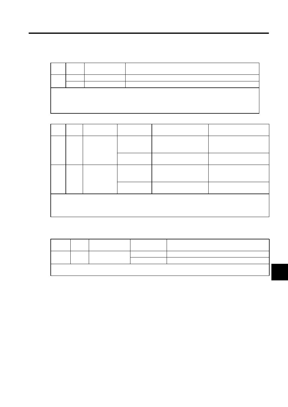
(2) Input Signals
8.9.5 Checking Output Torque Limiting during Operation
The following signal can be output to indicate that the servomotor output torque is being limited.
Type
Signal
Name
Connector Pin
Number
Name
Input
T-REF
CN1-1
Torque reference input
SG
CN1-2
Signal ground for torque reference input
The torque limit input gain is set in parameter Pn400. Refer to 8.7.1 Setting Parameters.
Input Specifications
• Input range:
±
1 VDC to
±
10 VDC/rated torque
• Maximum allowable input voltage:
±
12 VDC
Type
Signal
Name
Connector Pin
Number
Setting
Meaning
Limit Value
Input
/P-CL
CN1-11
(Factory setting)
ON (low level)
Forward external torque limit
ON
The analog voltage reference
limit or the value set in Pn402 or
Pn404 (whichever is smaller)
OFF (high level)
Forward external torque limit
OFF
Pn402
Input
/N-CL
CN1-12
(Factory setting)
ON (low level)
Reverse external torque limit
ON
The analog voltage reference
limit or the value set in Pn403 or
Pn405 (whichever is smaller)
OFF (high level)
Reverse external torque limit
OFF
Pn403
When using the torque limiting with the external torque limit and analog voltage reference, make sure that there are no
other signals allocated to the same terminals as /P-CL and /N-CL. When multiple signals are allocated to the same terminal,
the signals are handled with OR logic, which affects the ON/OFF state of the other signals. Refer to 7.3.2 Input Circuit Sig-
nal Allocation
.
Type
Signal
Name
Connector Pin
Number
Setting
Meaning
Output
/CLT
Must be allocated
ON (low level)
Servomotor output torque is being limited.
OFF (high level)
Torque is not being limited.
The output terminal must be allocated with parameter Pn50F to use this output signal. Refer to 7.3.3 Output Circuit Signal
Allocation for details.