2 wiring encoders, 1) incremental encoders – Yaskawa Sigma II Series DC Power Input SGMAJ User Manual
Page 124
6.2 Wiring Encoders
6-5
6
6.2 Wiring Encoders
The connection cables between encoder and SERVOPACK and wiring pin numbers differ depending on servo-
motor model. Refer to 5 Specifications and Dimensional Drawings of Cables and Peripheral Devices for details.
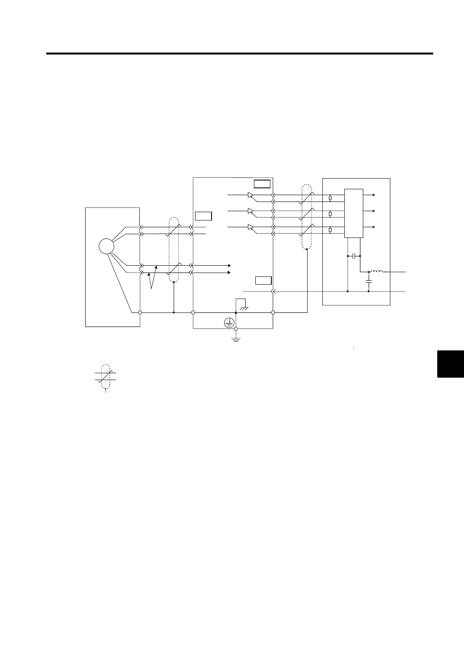
6.2.1 Connecting an Encoder (CN2) and Output Signals from the SERVOPACK
(CN1)
(1) Incremental Encoders
22
0 V
SG
1
0 V
0 V
+5 V
+5 V
PAO
/PAO
PBO
/PBO
PCO
/PCO
PG5V
PG0V
1
2
5
6
CN4
20
21
23
24
25
PG
CN1
0.33 mm
(0.001 in )
2
Light blue
PG
5 V
PG
0 V
PS
/PS
White/Light blue
Incremental
encoder
Red
Black
Shield wire
(Shell)
Connector shell
Connector
shell
Output line-driver SN75ALS194
manufactured by Texas
Instruments or the equivalent.
Phase A
Phase
A
Phase B
Phase
B
Phase C
Phase
C
SERVOPACK
Line receiver
Host controller
Choke
coil
Smoothing
capacitor
CN1
11
5
3
2
1
R
R
R
6
7
10
9
8
16
C
+
-
: represents twisted-pair wires.
2
∗
5
∗
∗
6
1
2
Applicable line receiver: SN75175 manufactured
by Texas Instruments or the
equivalent corresponding to MC3486.
R (terminator): 220 to 470
Ω
C (Decoupling Capacitor) 0.1
µF