48 (3) clear signal form selection, 4) clear operation selection – Yaskawa Sigma II Series DC Power Input SGMAJ User Manual
Page 221
8 Operation
8.6.1 Setting Parameters
8-48
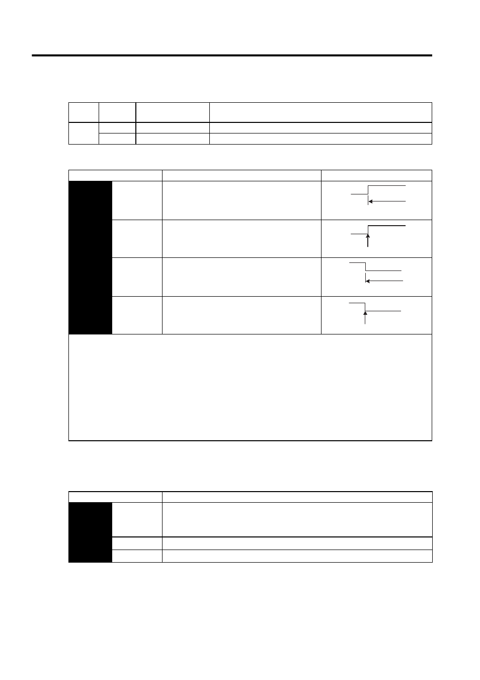
(3) Clear Signal Form Selection
The internal processing of the SERVOPACK for the clear signal can be set to either of four types by parameter
Pn200.1. Select according to the specifications of the machine or host controller.
(4) Clear Operation Selection
This parameter determines when the error pulse should be cleared according to the condition of the
SERVOPACK, in addition to the clearing operation of the clear signal (/CLR). Either of three clearing modes can
be selected with Pn200.2
Type
Signal
Name
Connector
Pin Number
Name
Input
CLR
CN1-5
Clear Input
/CLR
CN1-6
Clear Input
Parameter
Description
Timing
Pn200
n.0
Clears at high level.
Position error pulses do not accumulate while the
signal is at high level.
(Factory setting)
n.1
Clears at the rising edge.
n.2
Clears at low level.
Position error pulses do not accumulate while the
signal is at low level.
n.3
Clears at the falling edge.
The following are executed when the clear operation is enabled.
• The SERVOPACK error counter is set to 0.
• Position loop operation is disabled.
→ Holding the clear status may cause the servo clamp to stop functioning and the servomotor to rotate slowly due to drift
in the speed loop.
When the clear signal (CLR) is not wired, the signal is always at low level (does not clear).
When the clear signal (CLR) is not used and CN1-5, 6 are not wired, the CLR input terminals (CN1-5, 6) are always at high
level. The SERVOPACK is Pn200.1 factory set to clear position error pulse at high level. Even if a pulse train reference is
input with the setting in this state, the pulses will be constantly cleared and the motor will not operate. Set the parameter to
a value other than Pn200 = n.0, or short-circuit CN1-5, 6.
Clears at
high level
CLR
(CN1-5)
High
Clears here just once.
CLR
(CN1-5)
CLR
(CN1-5)
Clears at low level
Low
Clears here just once.
CLR
(CN1-5)
Parameter
Description
Pn200
n.0
(Factory
setting)
Clear the error pulse at the /CLR signal input during the baseblock.
“During the baseblock” means when the SVON signal or the main circuit power supply is
OFF, or an alarm occurs.
n.1
Do not clear the error pulse. Clear only with the /CLR signal.
n.2
Clear the error pulse when an alarm occurs or the /CLR signal is input.