Yaskawa Sigma II Series DC Power Input SGMAJ User Manual
Page 326
10.4 List of Parameters
10-45
10
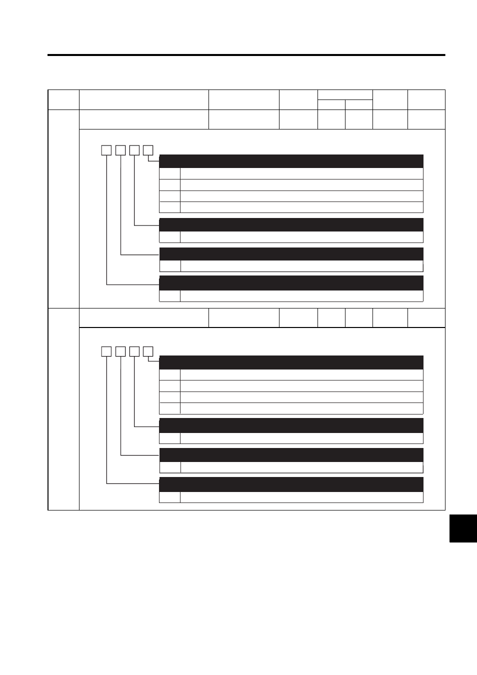
Pn50E
Output Signal Selections 1
−
−
3211
3211
After
restart
−
Pn50F
Output Signal Selections 2
−
−
0000
0000
After
restart
−
Parame-
ter No.
Name
Setting Range
Units
Factory Setting
Setting
Validation
Reference
Section
S P
0
1
2
3
0 to 3
Disabled (the above signal is not used.)
Outputs the signal from CN1-8, 10 output terminal.
Outputs the signal from CN1-9, 10 output terminal.
Outputs the signal from CN1-7, 10 output terminal.
Same as /COIN
Same as /COIN
Same as /COIN
Positioning Completion Signal Mapping (/COIN)
(Refer to "8.6.5 Positioning Completed Output Signal.")
Speed Coincidence Detection Signal Mapping (/V-CMP)
(Refer to "8.5.8 Speed Coincidence Output.")
Rotation Detection Signal Mapping (/TGON)
(Refer to "8.11.3 Running Output Signal (/TGON).")
Servo Ready Signal Mapping (/S-RDY)
(Refer to "8.11.4 Servo Ready (/S-RDY) Output.")
4th
digit
3rd
digit
2nd
digit
1st
digit
n.
0 to 3
0 to 3
0
1
2
3
0 to 3
Disabled (the above signal is not used.)
Outputs the signal from CN1-8, 10 output terminal.
Outputs the signal from CN1-9, 10 output terminal.
Outputs the signal from CN1-7, 10 output terminal.
Same as /CLT
Same as /CLT
Same as /CLT
Torque Limit Detection Signal Mapping (/CLT)
(Refer to "8.9.5 Checking Output Torque Limiting during Operation.")
Speed Limit Detection Signal Mapping (/VLT)
(Refer to "8.7.4 Limiting Servomotor Speed during Torque Control.")
Brake Interlock Signal Mapping (/BK)
(Refer to "8.3.4 Setting for Holding Brakes.")
4th
digit
3rd
digit
2nd
digit
1st
digit
n.
0 to 3
0 to 3
Warning Signal Mapping (/WARN)
(Refer to "8.11.2 Warning Output (/WARN).")