Yaskawa Sigma II Series DC Power Input SGMAJ User Manual
Page 287
10 Inspection, Maintenance, and Troubleshooting
10.1.3 Troubleshooting of Alarm and Warning
10-6
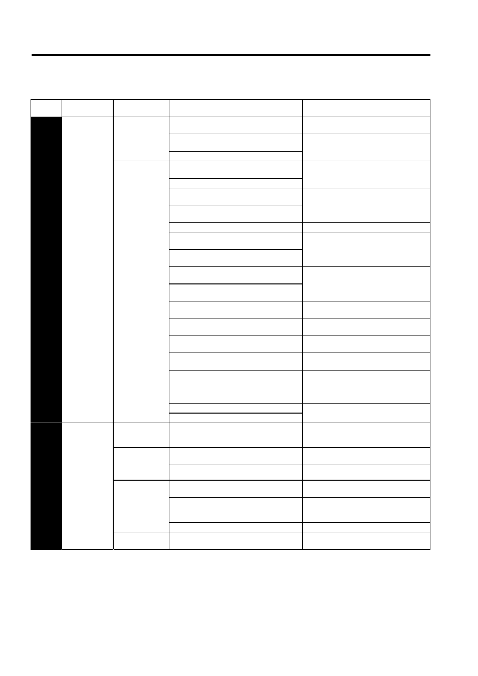
A.10
Overcurrent
(An overcurrent
flowed through
the MOS-FET)
or Heat Sink
Overheated
Occurred when the
control power sup-
ply was turned ON.
The overload alarm has been reset by turning OFF
the power too many times.
Change the method to reset the alarm.
The connection is faulty between the SERVOPACK
board and the thermostat switch.
Replace the SERVOPACK.
The SERVOPACK board fault occurred.
Occurred when the
main circuit power
supply was turned
ON or when an
overcurrent
occurred while the
servomotor was
running.
The connection between grounding and U, V, or W
is incorrect.
Check and then correct the wiring.
The grounding line has contact with other terminals.
A short circuit occurred between the grounding and
U, V, or W of the servomotor cable.
Repair or replace the servomotor main circuit
cable.
A short circuit occurred between phases U, V, and W
of the servomotor.
The wiring of the regenerative resistor is incorrect.
Check and then correct the wiring.
A short circuit occurred between the grounding and
U, V, or W of the SERVOPACK.
Replace the SERVOPACK.
A SERVOPACK fault occurred (current feedback
circuit, power transistor or board fault).
A short circuit occurred between the grounding and
U, V, W of the servomotor.
Replace the servomotor.
A short circuit occurred between phases U, V, and W
of the servomotor.
The dynamic brake was activated too frequently, so
a DB overload alarm occurred.
Replace the SERVOPACK, and reduce the DB
operation frequency.
The overload alarm has been reset by turning OFF
the power too many times.
Change the method to reset the alarm.
The excessive change was given to the position/
speed reference.
Recheck the reference value.
The overload or regenerative power exceeds the
regenerative resistor’s capacity.
Reconsider the load and operation conditions.
The direction or the distance of the SERVOPACK to
other devices is incorrect.
Heat radiation of the panel or heat around the panel
occurred.
The ambient temperature for the SERVOPACK
must be 40
°C or less.
A SERVOPACK fan fault occurred.
Replace the SERVOPACK.
A SERVOPACK fault occurred.
A.40
Overvoltage
∗
1
(Detected when
the DC voltage
of the
SERVOPACK’s
main circuit is 33
VDC for the 24
VDC model and
60 VDC or more
for the 480 VDC
model.)
(Detected when
the power to the
main circuit is
turned ON.)
Occurred when the
control power sup-
ply was turned ON.
A SERVOPACK board fault occurred.
Replace the SERVOPACK.
Occurred when the
main circuit power
supply was turned
ON.
The DC power voltage is too high.
The DC power voltage must be within the speci-
fied range.
A SERVOPACK fault occurred.
Replace the SERVOPACK.
Occurred during
normal operation.
Check the DC power voltage (check if there is no
excessive voltage change.)
The DC power voltage must be within the speci-
fied range.
The motor speed is high and load moment of inertia
is excessive, resulting in insufficient regenerative
capacity.
Check the load moment of inertia and minus load
specifications. Reconsider the load and operation
conditions.
A SERVOPACK fault occurred.
Replace the SERVOPACK.
Occurred at servo-
motor deceleration.
The motor speed is high, and the load moment of
inertia is excessive.
Reconsider the load and operation conditions.
Table 10.3 Alarm Display and Troubleshooting (cont’d)
Alarm
Display
Alarm Name
Situation at Alarm
Occurrence
Cause
Corrective Actions