Yaskawa Sigma II Series DC Power Input SGMAJ User Manual
Page 297
10 Inspection, Maintenance, and Troubleshooting
10.1.4 Troubleshooting for Malfunction without Alarm Display
10-16
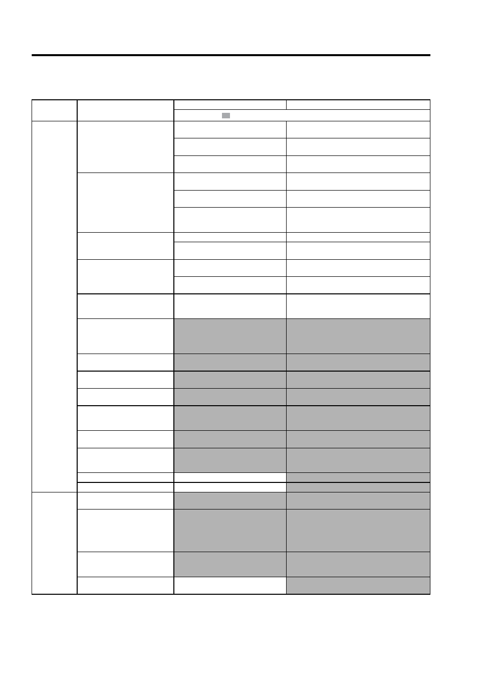
Overtravel
(OT)
(Movement
over the zone
specified by
the host con-
troller)
An overtravel signal is output (P-OT
(CN1-16) or N-OT (CN1-17)) is at
H.
Check if the voltage of input signal external
power supply (+24 V) is correct.
Connect to the external +24 V power supply.
Check if the overtravel limit switch (SW)
operates properly.
Correct the overtravel limit SW.
Check if the overtravel limit switch (SW) is
connected correctly.
Correct the overtravel limit SW wiring.
The overtravel signal does not oper-
ate normally (P-OT or N-OT signal
sometimes changes).
Check the fluctuation of the input signal
external power supply (+24 V) voltage.
Stabilize the external +24 V power supply voltage.
Check if the overtravel limit switch (SW)
activate correctly.
Adjust the overtravel limit SW so that it operates cor-
rectly.
Check if the overtravel limit switch wiring
is correct. (check for damaged cables or
loosen screws.)
Correct the overtravel limit SW wiring.
Incorrect P-OT/N-OT signal selec-
tion
Check the P-OT signal selection (Pn50A.3).
Correct the setting of P-OT signal selection (Pn50A.3).
Check the N-OT signal selection
(Pn50B.0).
Correct the setting of N-OT signal selection (Pn50B.0).
Incorrect servomotor stop method
selection
Check if “coast to stop” in servo OFF status
is selected.
Check Pn001.0 and Pn001.1.
Check if “coast to stop” in torque control
mode is selected.
Check Pn001.0 and Pn001.1.
Improper overtravel position setting
The distance to the position of OT
(overtravel) is too short considering the
coasting distance.
Correct the OT position.
Noise interference due to improper
encoder cable specifications
The encoder cable specifications must be:
Twisted-pair or twisted-pair shielded wire
with core 0.12 mm
2
(0.0002 in
2
) min. and
tinned annealed copper twisted wire.
Use encoder cable with the specified specifications.
Noise interference because the
encoder cable distance is too long.
The wiring distance must be 20 m (65.6 ft)
max.
The encoder cable distance must be within the specified
range.
Noise influence due to damaged
encoder cable
Check if the encoder cable is bent or its
sheath is damaged.
Correct the encoder cable layout.
Excessive noise interference to
encoder cable
Check if the encoder cable is bundled with a
high-current line or near high-current line.
Change the encoder cable layout so that no surge is
applied.
FG electrical potential varies by
influence of such machines on the
servomotor side as welders.
Check if the machine is correctly grounded.
Ground the machine separately from PG side FG.
SERVOPACK pulse count error due
to noise
Check if the signal line from the encoder is
influenced by noise.
Take a measure against noise for the encoder wiring.
Excessive vibration and shock to the
encoder
Machine vibration occurred or servomotor
mounting such as mounting surface preci-
sion, fixing, alignment is incorrect.
Reduce the machine vibration or mount the servomotor
securely.
Encoder fault
An encoder fault occurred.
Replace the servomotor.
SERVOPACK fault
A SERVOPACK fault occurred.
Replace the SERVOPACK.
Position error
(without
alarm)
Unsecured coupling between
machine and servomotor
Check if a position error occurs at the cou-
pling between machine and servomotor.
Secure the coupling between the machine and servomo-
tor.
Noise interference due to improper
input signal cable specifications
The input signal cable specifications must
be:
Twisted-pair or twisted-pair shielded wire
with core 0.12 mm
2
(0.0002 in
2
) min. and
tinned annealed copper twisted wire.
Use input signal cable with the specified specifications.
Noise interference because the input
signal cable distance is too long.
The wiring distance must be 3 m (9.84 ft)
max. and the impedance several hundreds
ohm max.
The input signal cable distance must be within the speci-
fied range.
Encoder fault (pulse count does not
change)
An encoder fault occurred. (pulse count
does not change)
Replace the servomotor.
Table 10.5 Troubleshooting for Malfunction without Alarm Display (cont’d)
Symptom
Cause
Inspection
Corrective Actions
: Turn OFF the servo system before executing operations.