2 servopack ratings and specifications 2 – Yaskawa Sigma II Series DC Power Input SGMAJ User Manual
Page 87
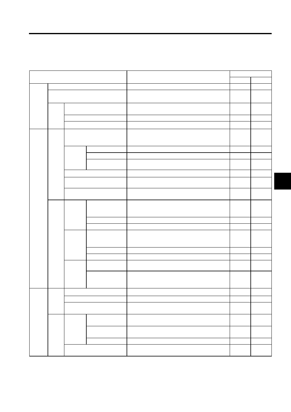
4.1 SERVOPACK Ratings and Specifications
4-3
4
4.1.2 SERVOPACK Ratings and Specifications 2
Item
Ratings and Specifications
SGDJ-
S
P
Basic
Specifi-
cations
Control Method
MOSFET-PWM method
Applicable Applicable
Feedback
Serial encoder: 13, 16 or 17-bit (incremental/absolute)
∗
The 13-bit encoder is incremental only.
Applicable Applicable
Condi-
tions
Ambient/Storage Temperature
∗1
0
°C to 40 °C (32 °F to 104 °F) (Including the internal
panel use)/-20
°C to +85 °C (-4 °F to 185 °F)
Applicable Applicable
Ambient/Storage Humidity
90
% RH or less (with no condensation)
Applicable Applicable
Vibration/Shock Resistance
9.8 m/s
2
/147 m/s
2
Applicable Applicable
Speed
and
Torque
Control
Modes
Perfor-
mance
Speed Control Range
1:5000 (The lowest speed of the speed control range is
the speed at which the servomotor will not stop with a
rated torque load.)
Applicable
N/A
Speed
Regula-
tion
∗2
Load Regulation
0 to 100
% load: ±0.01% or less (at rated speed)
Applicable
N/A
Voltage Regulation
Rated voltage
±10%: 0% (at rated speed)
Applicable
N/A
Temperature Regula-
tion
25
± 25 °C (77 °F): ±0.1% or less (at rated speed)
Applicable
N/A
Frequency Characteristics
400 Hz (at J
L
= J
M
)
Applicable
N/A
Torque Control Tolerance
(Repeatability)
±2%
Applicable
N/A
Soft Start Time Setting
0 to 10 s (Can be set individually for acceleration and
deceleration.)
Applicable
N/A
Input
Signals
Speed
Reference
Input
Reference Voltage
∗3
±6 VDC (Variable setting range: ±2 to ±10 VDC) at
rated torque (servomotor forward rotation with positive
reference), input voltage: maximum
±12 V
Applicable
N/A
Input Impedance
About 14 k
Ω
Applicable
N/A
Circuit Time Constant
About 47
µs
Applicable
N/A
Torque
Reference
Input
Reference Voltage
∗3
±3 VDC (Variable setting range: ±1 to ±10 VDC) at
rated torque (positive torque reference with positive ref-
erence), input voltage: maximum
±12 V
Applicable
N/A
Input Impedance
About 14 k
Ω
Applicable
N/A
Circuit Time Constant
About 47
µs
Applicable
N/A
Contact
Speed
Reference
Rotation Direction
Selection
With P control signal
Applicable
N/A
Speed Selection
With forward/reverse current limit signal (speed 1 to 3
selection), servomotor stops or another control method
is used when both are OFF.
Applicable
N/A
Position
Control
Modes
Perfor-
mance
Bias Setting
0 to 450 min
-1
(setting resolution: 1 min
-1
)
N/A
Applicable
Feed Forward Compensation
0 to 100
% (setting resolution: 1%)
N/A
Applicable
Positioning Completed Width
Setting
0 to 250 reference units (setting resolution: 1 reference
unit)
N/A
Applicable
Input
Signals
Reference
Pulse
Type
Sign + pulse train, 90
° phase difference 2-phase pulse
(phase A + phase B), or CCW + CW pulse train
N/A
Applicable
Form
Line driver (+5 V level), open collector (+5 V or +12 V
level)
N/A
Applicable
Frequency
Maximum 500/200 kpps (line driver/open collector)
N/A
Applicable
Control Signal
Clear signal (input pulse form identical to reference
pulse)
N/A
Applicable