5 positioning completed output signal – Yaskawa Sigma II Series DC Power Input SGMAJ User Manual
Page 230
8.6 Operating Using Position Control
8-57
8
8.6.5 Positioning Completed Output Signal
This signal indicates that servomotor movement has been completed during position control. Use the signal as an
interlock to confirm at the host controller that positioning has been completed.
Type
Signal
Name
Connector
Pin Number
Setting
Meaning
Output
/COIN
CN1-8, 10
(Factory setting)
ON (low level)
Positioning has been completed.
OFF (high level) Positioning is not completed.
This output signal can be allocated to an output terminal with parameter Pn50E. Refer to 7.3.3 Output Circuit Signal Allo-
cation for details. The factory setting is allocated to CN1-8, 10.
Pn500
Positioning Completed Width
Setting Range
Setting Unit
Factory Setting
Setting Validation
0 to 250
Reference units
7
Immediately
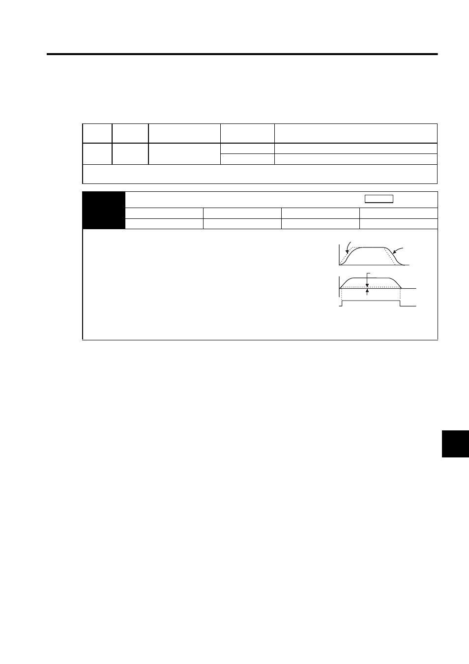
The positioning completed (/COIN) signal is output when the difference
(position error pulse) between the number of reference pulses output by
the host controller and the travel distance of the servomotor is less than
the value set in this parameter.
Set the number of error pulses in reference units (the number of input
pulses defined using the electronic gear.)
Too large a value at this parameter may output only a small error during
low-speed operation that will cause the /COIN signal to be output con-
tinuously.
If a servo gain is set that keeps the position error small even when the
positioning completed width is large, use Pn207 = n.1 to enable correct output timing for the COIN signal.
The positioning completed width setting has no effect on final positioning accuracy.
Position
Speed
Reference
Motor speed
/COIN
(CN1-8)
Error pulse
(Un008)
Pn500