3) detailed signal specifications, A) pao serial data specifications – Yaskawa Sigma II Series DC Power Input SGMAJ User Manual
Page 205
8 Operation
8.4.6 Absolute Encoder Reception Sequence
8-32
Final absolute data P
M
is calculated by following formula.
(3) Detailed Signal Specifications
(a) PAO Serial Data Specifications
The number of revolutions is output in five digits.
Note: 1. Data is “P+00000” (CR) or “P-00000” (CR) when the number of revolutions is zero.
2. The revolution range is “+32767” to “-32768.” When this range is exceeded, the data
changes from “+32767” to “-32678” or from “-32678” to “+32767.” When changing
multiturn limit, the range changes. For details, refer to 8.4.7 Multiturn Limit Setting.
P
E
Current value read by encoder
P
E
= M × R + P
O
P
M
= P
E
- P
S
M
Multiturn data (rotation count data)
P
O
Number of initial incremental pulses
Use the following for reverse rotation
mode (Pn000.0 = 1).
P
E
= -M × R + P
O
P
M
= P
E
- P
S
P
S
Number of initial incremental pulses read at setup (This is saved and
controlled by the host controller.)
P
M
Current value required for the user’s system
R
Number of pulses per encoder revolution (pulse count after dividing,
value of Pn201)
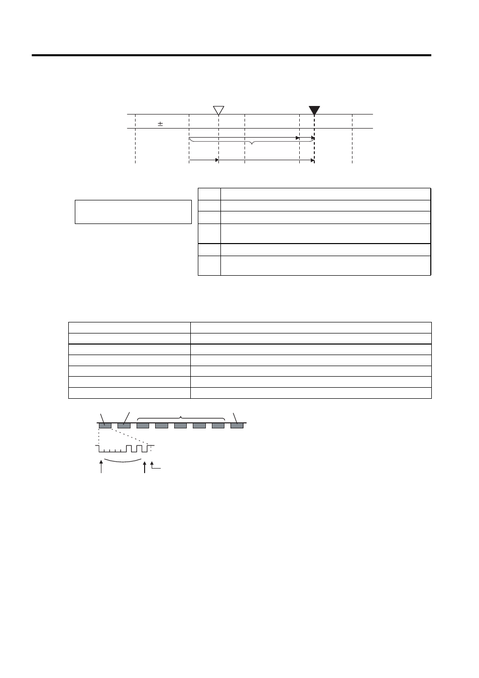
Coordinate
value
Value M
Reference position (setup)
- 1
0
+1
+2
+3
+3
Current position
+2
+1
0
P
E
P
M
P
S
P
O
M
×R
Data Transfer Method
Start-stop Synchronization (ASYNC)
Baud rate
9600 bps
Start bits
1 bit
Stop bits
1 bit
Parity
Even
Character code
ASCII 7-bit code
Data format
8 characters, as shown below.
Data
Start bit
Even parity
"+" or "- "
"0" to "9"
"CR"
"P"
Stop bit
0 0 0 0 0 1 0 1 0 1