Yaskawa Sigma II Series DC Power Input SGMAJ User Manual
Page 166
7 Digital Operator
7.3.2 Input Circuit Signal Allocation
7-22
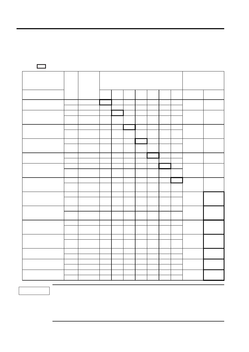
(2) Changing the Allocation (Pn50A.0 = 1)
Set the parameter in accordance with the relation between the signal to be used and the input connector pin.
After having changed the parameter, turn OFF the power and ON again to enable the parameters.
means factory setting.
1. When using Servo ON, Forward Run Prohibited, and Reverse Run Prohibited signals with the setting
“Polarity Reversal,” the machine may not move to the specified safe direction at occurrence of failure
such as signal line disconnection. If such setting is absolutely necessary, confirm the operation and
observe safety precautions.
2. When two or more signals are allocated to the same input circuit, the input signal level will be applied to
all the allocated signal.
Signal Name
Valid-
ity
Level
Input
Signal
CN1 Input Pin Allocation
Connection Not
Required
(SERVOPACK judges
the connection)
Parameter Setting
Allocation
14
15
16
17
18
11
12
Always
ON
Always
OFF
Servo ON
Pn50A.1 = n.xxx
L
/S-ON
0
1
2
3
4
5
6
7
8
H
S-ON
9
A
B
C
D
E
F
Proportional Operation
Reference
Pn50A.2 = n.xxx
L
/P-CON
0
1
2
3
4
5
6
7
8
H
P-CON
9
A
B
C
D
E
F
Forward Run
Prohibited
Pn50A.3 = n.xxx
H
P-OT
0
1
2
3
4
5
6
7
8
L
/P-OT
9
A
B
C
D
E
F
Reverse Run
Prohibited
Pn50B.0 = n.xxx
H
N-OT
0
1
2
3
4
5
6
7
8
L
/N-OT
9
A
B
C
D
E
F
Alarm Reset
Pn50B.1 = n.xxx
L
/ARM-RST
0
1
2
3
4
5
6
−
8
H
ARM-RST
9
A
B
C
D
E
F
Forward External
Torque Limit
Pn50B.2 = n.xxx
L
/P-CL
0
1
2
3
4
5
6
7
8
H
P-CL
9
A
B
C
D
E
F
Reserve External
Torque Limit
Pn50B.3 = n.xxx
L
/N-CL
0
1
2
3
4
5
6
7
8
H
N-CL
9
A
B
C
D
E
F
Internal Set Speed
Selection
Pn50C.0 = n.xxx
L
/SPD-D
0
1
2
3
4
5
6
7
8
H
SPD-D
9
A
B
C
D
E
F
Internal Set Speed
Selection
Pn50C.1 = n.xxx
L
/SPD-A
0
1
2
3
4
5
6
7
8
H
SPD-A
9
A
B
C
D
E
F
Internal Set Speed
Selection
Pn50C.2 = n.xxx
L
/SPD-B
0
1
2
3
4
5
6
7
8
H
SPD-B
9
A
B
C
D
E
F
Control Method
Selection
Pn50C.3 = n.xxx
L
/C-SEL
0
1
2
3
4
5
6
7
8
H
C-SEL
9
A
B
C
D
E
F
Zero Clamp
Pn50D.0 = n.xxx
L
/ZCLAMP
0
1
2
3
4
5
6
7
8
H
ZCLAMP
9
A
B
C
D
E
F
Reference Pulse Inhibit
Pn50D.1 = n.xxx
L
/INHIBIT
0
1
2
3
4
5
6
7
8
H
INHIBIT
9
A
B
C
D
E
F
Gain Changeover
Pn50D.2 = n.xxx
L
/G-SEL
0
1
2
3
4
5
6
7
8
H
G-SEL
9
A
B
C
D
E
F
IMPORTANT