Yaskawa Sigma II Series DC Power Input SGMAJ User Manual
Page 306
10.3 Connection to Host Controller
10-25
10
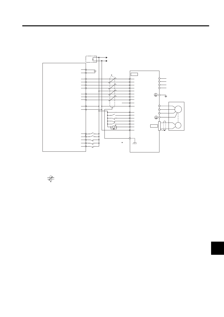
10.3.6 Example of Connection to OMRON’s Position Control Unit
* 1. The ALM signal is output for about two seconds after the control power is turned ON. Take this into
consideration when designing the power ON sequence. The ALM signal actuates the alarm detection
relay 1Ry to stop the main circuit power supply to the SERVOPACK.
* 2. Connect the shield wire to the connector shell.
* 3.
represents twisted-pair wires.
Note: Only signals applicable to OMRON’s MC unit (positioning unit) and Yaskawa’s SGDJ-P
SERVOPACK are shown in the diagram.
CN2
CN1
A3
A5
A6
A7
A4
2
25
8
C1
L2
L1
C2
24
4
1
6
5
W
V
1
2
3
4
U
Position control unit
Servomotor
SGDJ-P
SERVOPACK
CS1W-NC133 / 233 / 433
manufactured by OMRON
A16
A11
A14
A1
A2
A8
A20
A22
A23
A21
A19
3
/SIGN
CLR
/CLR
PCO
PULS
/PULS
SIGN
/PCO
COIN+
SG 10
34
35
18
16
17
13
14
+24V-IN
/S-ON
P-OT
N-OT
/ALM-RST
ALM-
ALM+
1Ry
1
3
4
5 VDC
5V power supply for pulse output
5V GND for pulse output
24 V power supply for output
24 V GND for output
CCW(+) output
CCW(-) output
CW(+) output
CW(-) output
Origin input signal
Origin input common
Error counter reset output
X-axis CW limit input
X-axis CCW limit input
X-axis immediate stop input
X-axis origin proximity input
X-axis external interrupt input
Connector
shell
M
PG
+
-
+24V
0
24
+24
V
I/O power supply
Control power supply
Main circuit power supply