4 setting for holding brakes, 1) wiring example, Important – Yaskawa Sigma II Series DC Power Input SGMAJ User Manual
Page 195
8 Operation
8.3.4 Setting for Holding Brakes
8-22
8.3.4 Setting for Holding Brakes
The holding brake is used when a SERVOPACK controls a vertical axis. In other words, a servomotor with
brake prevents the movable part from shifting due to gravity when the SERVOPACK power goes OFF. (Refer to
8.1.4 Servomotor with Brakes.)
1. The brake built into the servomotor with brakes is a deenergization brake, which is used only to hold and
cannot be used for braking. Use the holding brake only to hold a stopped motor. Brake torque is at least
120% of the rated motor torque.
2. When operating using only a speed loop, turn OFF the servo and set the input reference to 0 V when the
brake is applied.
3. When forming a position loop, do not use a mechanical brake while the servomotor is stopped because
the servomotor enters servolock status.
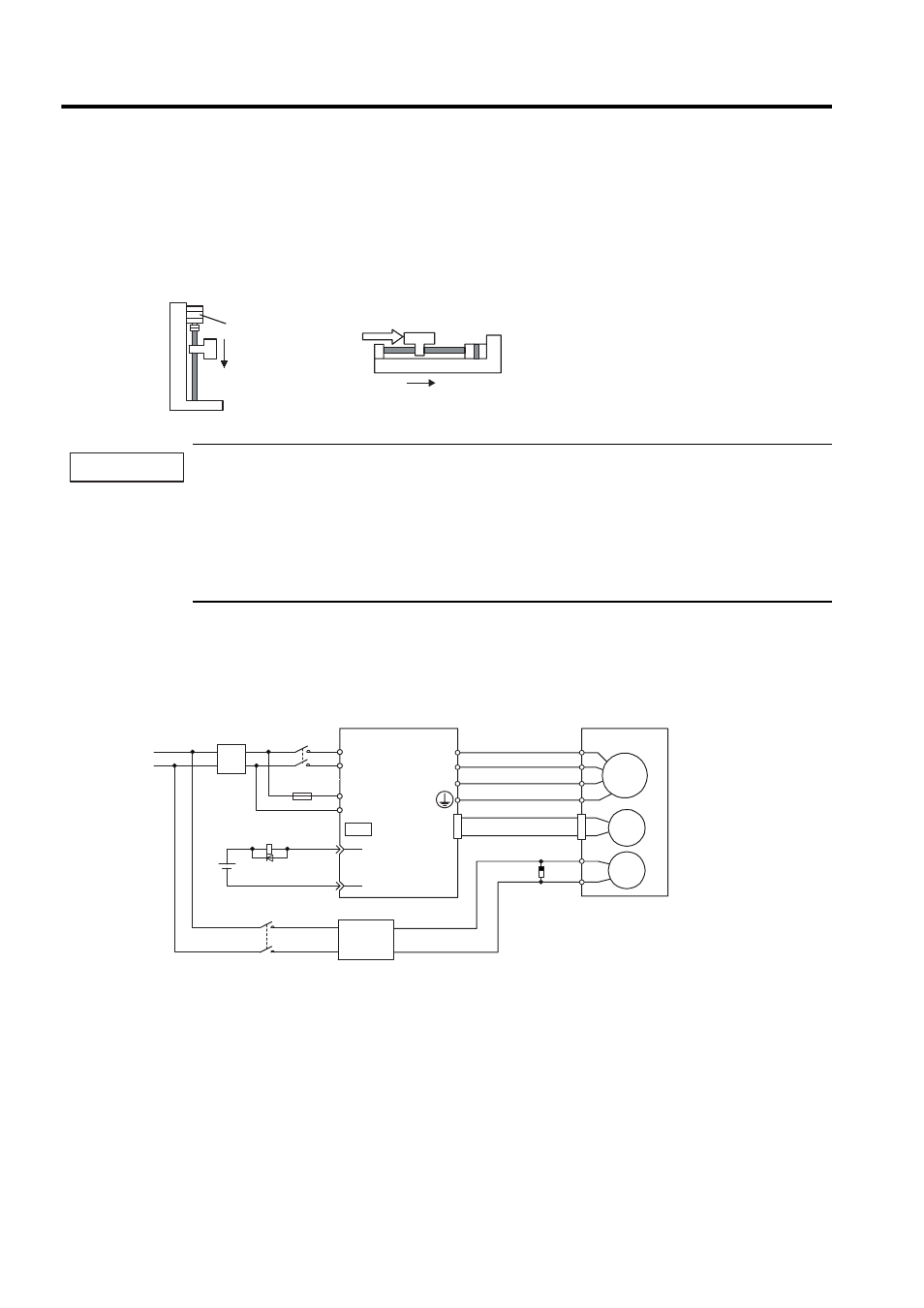
(1) Wiring Example
Use the SERVOPACK contact output signal /BK and the brake power supply to form a brake ON/OFF circuit.
The following diagram shows a standard wiring example.
Servomotor
zVertical Shaft
Holding brake
Prevents the servomotor
from shifting when
the power is OFF.
zShaft with External Force Applied
Servomotor
External
force
Prevents the servomotor from
shifting due to external force.
IMPORTANT
Servomotor
with brake
SERVOPACK
Power supply
BK-RY: Brake control relay
AC/DC converter: The brakes of SGMMJ and SGMAJ SERVOPACK are 24 VDC.
The customer must provide the 24-VDC output power supply.
∗1 and ∗2 are the output terminals allocated with Pn50F.2.
Surge suppressor
CR50500BL
(Manufactured by
Okaya Electric
Industries Co., Ltd.)
M
BK
PG
U
V
W
CN4
BK-RY
BK-RY
+24V
L1
L2
10
C1
C2
(/BK+)
SG
CN1
∗
R
T
AC/DC
converter
AC/DC
converter