2 starting and stopping time, 3 load moment of inertia – Yaskawa Sigma II Series DC Power Input SGMAJ User Manual
Page 95
4.5 SERVOPACK Overload Characteristics and Allowable Load Moment of Inertia
4-11
4
4.5.2 Starting and Stopping Time
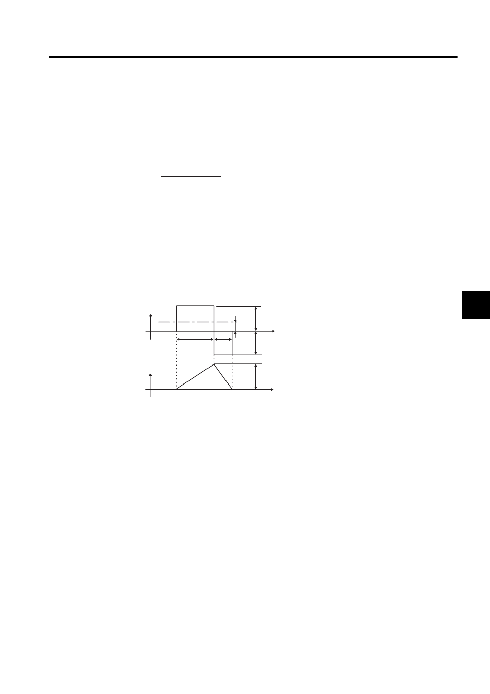
The motor starting time (tr) and stopping time (tf) under a constant load are calculated using the following for-
mulas. Motor viscous torque and friction torque are ignored.
Calculate the torque from the motor current using servomotor torque constant
× motor current (effective value).
The following figure shows the motor torque and motor speed timing chart.
4.5.3 Load Moment of Inertia
The larger the load moment of inertia, the worse the movement response of the load.
The size of the load moment of inertia (J
L
) allowable when using a servomotor depends on motor capacity and is
limited to within 30 times the moment of inertia of each servomotor (J
M
). This value is provided strictly as a
guideline and results may vary depending on servomotor drive conditions.
An overvoltage alarm is likely to occur during deceleration if the load moment of inertia exceeds the allowable
load moment of inertia. Take one of the following steps if this occurs.
• Reduce the torque limit.
• Reduce the deceleration rate.
• Reduce the maximum motor speed.
N
M
:
Motor speed (min
-1
)
J
M
:
Motor rotor moment of inertia (kgxm
2
)
J
L
:
Load converted to shaft moment of inertia (kgxm
2
)
T
PM
:
Instantaneous peak motor torque when combined with a SERVOPACK (Nxm)
T
L
:
Load torque (Nxm)
tr =
tf =
Starting time:
Stopping time:
2
π x N
M
(J
M
+ J
L
)
x
(T
PM
x T
L
)
60
[s]
[s]
2
π x N
M
(J
M
+ J
L
)
x
(T
PM
x T
L
)
60
Motor torque
(current amplitude)
Motor speed
tr
tf
N
M
T
PM
T
L
Time
Time
T
PM