Yaskawa Sigma II Series DC Power Input SGMAJ User Manual
Page 292
10.1 Troubleshooting
10-11
10
* 1. This alarm occurs when the communications is still disabled five seconds after digital opera-
tor power supply is ON, or when digital operator communications disabled status stays while
an application module is connected.
* 2. This alarm occurs when digital operator received data error occurs consecutively five times,
or when the state that digital operator receives no data from SERVOPACK for one second or
more occurs consecutively three times.
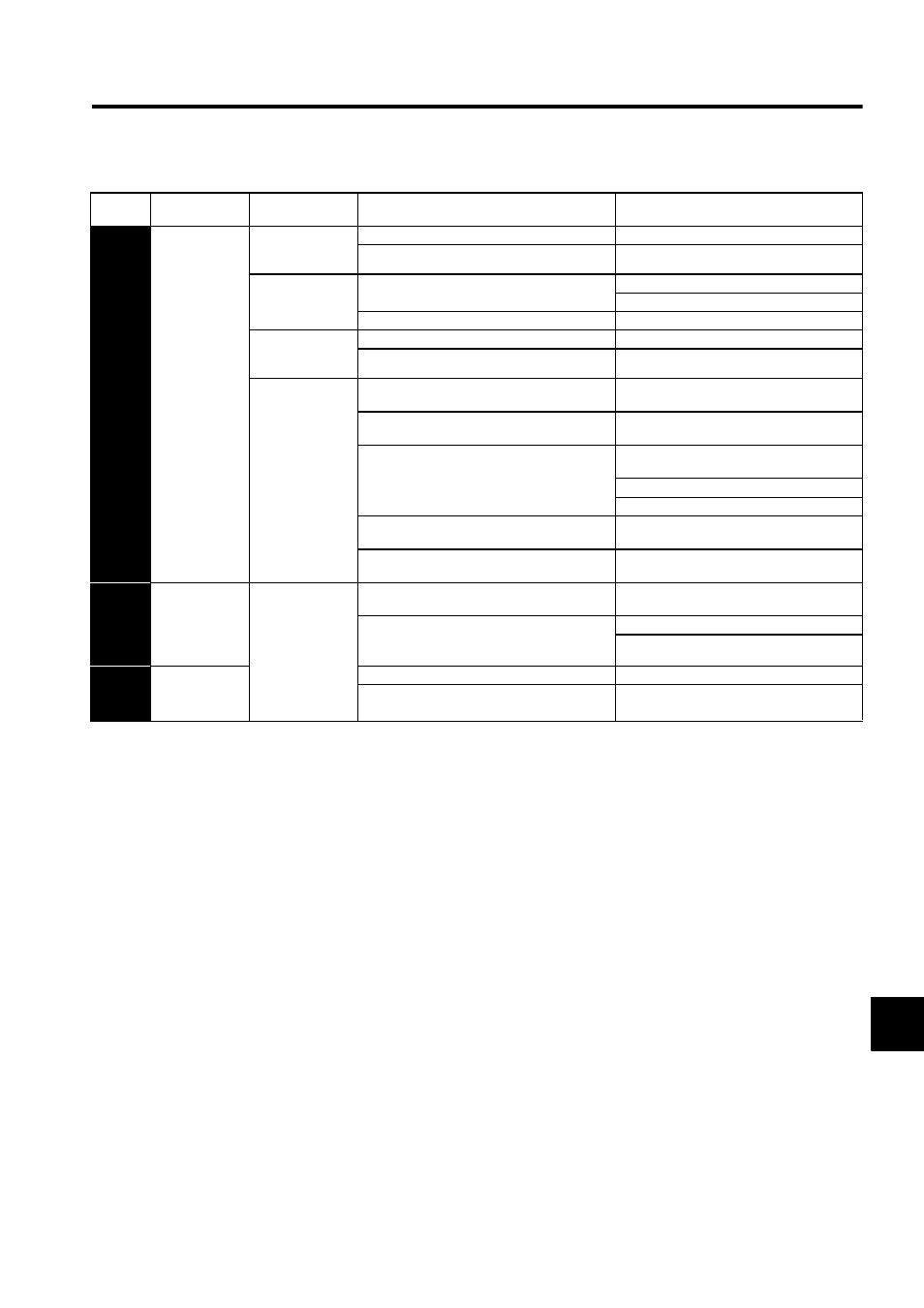
A.d0
Position Error
Pulse Overflow
(In servo ON sta-
tus, the position
error pulses
exceed the over-
flow level set in
the parameter
Pn505.)
Occurred when the
control power sup-
ply was turned ON.
The overflow level (Pn505) is incorrect.
Make the value set in the Pn505 to other than 0.
A SERVOPACK board fault occurred.
Replace the SERVOPACK.
Occurred at the ser-
vomotor high-speed
rotation.
The contact in the servomotor U, V, and W wirings
is faulty.
Correct the servomotor wiring.
Correct the encoder wiring.
A SERVOPACK board fault occurred.
Replace the SERVOPACK.
The servomotor did
not run with posi-
tion reference input.
Wirings of the servomotor U, V, and W are incorrect.
Correct the servomotor wiring.
A SERVOPACK board fault occurred.
Replace the SERVOPACK.
Normal movement,
but occurred with a
long distance refer-
ence input.
The SERVOPACK gain adjustment is improper.
Increase the speed loop gain (Pn100) and position
loop gain (Pn102).
The V-REF input voltage and the Pn300 setting are
incorrect.
Lower the reference speed to the speed limit
value.
The position reference pulse frequency is too high.
Adjust slowly the position reference pulse fre-
quency.
Apply the smoothing function.
Correct the electronic gear ratio.
Setting of the position error pulse overflow alarm
level (Pn505) is incorrect.
Set the parameter Pn505 to proper value.
The servomotor specifications do not meet the load
conditions such as torque and moment of inertia.
Reconsider and correct the load and servomotor
capacity.
CPF00
Digital Opera-
tor Transmis-
sion Error 1
∗
2
Occurred when the
power supply was
turned ON with dig-
ital operator con-
nected or
when connecting
digital operator with
the power supply
was turned ON.
The contact between the digital operator and the
SERVOPACK is faulty.
Insert securely the connector, or replace the cable.
The external noise interference occurred to the digi-
tal operator or cable.
(The digital operator cable is near noise source.)
Do not lay the cable near noise source.
Install digital operator far from noise source.
CPF01
Digital Opera-
tor Transmis-
sion Error 2
∗
3
A digital operator fault occurred.
Replace the digital operator.
A SERVOPACK fault occurred.
Replace the SERVOPACK.
Table 10.3 Alarm Display and Troubleshooting (cont’d)
Alarm
Display
Alarm Name
Situation at Alarm
Occurrence
Cause
Corrective Actions