Yaskawa Sigma II Series DC Power Input SGMAJ User Manual
Page 294
10.1 Troubleshooting
10-13
10
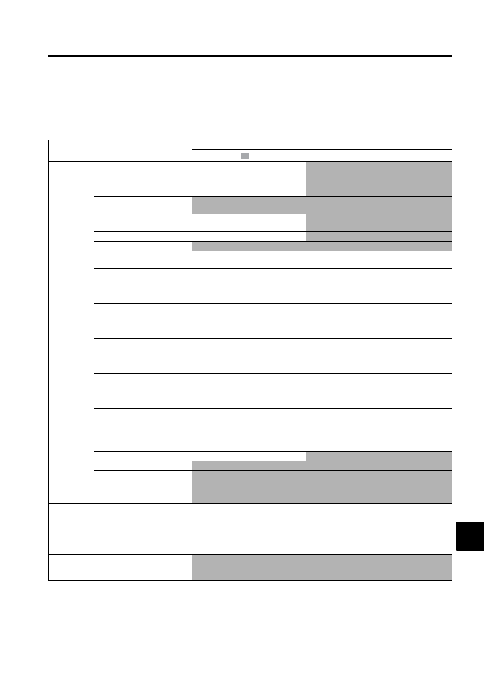
10.1.4 Troubleshooting for Malfunction without Alarm Display
The troubleshooting for the malfunctions that causes no alarm display is listed below.
Contact your Yaskawa representative if the problem cannot be solved by the described corrective actions.
Table 10.5 Troubleshooting for Malfunction without Alarm Display
Symptom
Cause
Inspection
Corrective Actions
: Turn OFF the servo system before executing operations.
Servomotor
Does Not
Start
The control power supply is not ON.
Check voltage between control power sup-
ply terminals.
Correct the control power circuit.
The main circuit power supply is not
ON.
Check the voltage between power supply
terminals.
Correct the power circuit.
Wrong wiring or disconnection of
I/O signal connector CN1
Check if the connector CN1 is properly
inserted and connected.
Correct the connector CN1 connection.
Servomotor or encoder wiring dis-
connected.
Check the wiring.
Correct the wiring.
Overloaded
Run under no load.
Reduce load or replace with larger capacity servomotor.
Speed/position references not input
Check reference input pins.
Input speed/position references correctly.
Setting for Pn50A to Pn50D “Input
Signal Selection” is incorrect.
Check settings of parameters Pn50A to
Pn50D.
Correct the settings for Pn50A to Pn50D “Input Signal
Selection.”
Encoder type differs from parameter
setting.
Check incremental or absolute encoder.
Set parameter Pn002.2 to the encoder type being used.
/S-ON input signal stays OFF.
Check settings of parameters Pn50A.0 and
Pn50A.1.
Correct the parameter setting and turn ON /S-ON input
signal.
/P-CON input function setting is
incorrect.
Check parameter Pn001.1.
Set parameters to match the application.
SEN input is turned OFF.
Check the SEN signal input (when absolute
encoder is used).
Turn SEN input signal ON.
Reference pulse mode selection is
incorrect.
Check the parameter setting for the refer-
ence pulse mode.
Correct setting of parameter Pn200.0.
Speed control: Speed reference input
is incorrect.
Check V-REF and SG to confirm if the con-
trol method and the input are agreed.
Correct the control mode selection parameter, or the
input.
Torque control: Torque reference
input is incorrect.
Check V-REF and SG to confirm if the con-
trol method and the input are agreed.
Correct the control mode selection parameter, or the
input.
Position control: Reference pulse
input is incorrect.
Check Pn200.0 reference pulse form or sign
+ pulse signal.
Correct the control mode selection parameter, or the
input.
The error clear counter (CLR) input
is turned ON.
Check CLR or /CLR input pins (CN1-14
and -15).
Turn CLR or /CLR input signal OFF.
The forward run prohibited (P-OT)
or reverse run prohibited (N-OT)
input signal is turned OFF.
Check P-OT or N-OT input signal.
Turn P-OT or N-OT input signal ON.
A SERVOPACK fault occurred.
A SERVOPACK board fault occurred.
Replace the SERVOPACK.
Servomotor
Moves In-
stantaneous-
ly, and then
Stops
Servomotor wiring is incorrect.
Check the servomotor wiring.
Correct the servomotor wiring.
Encoder wiring is incorrect.
Check the encoder wiring.
Correct the encoder wiring.
Servomotor
Suddenly
Stops during
Operation
and will Not
Restart
An alarm occurred while alarm reset
signal (ALM-RST) was turned ON.
Check the alarm reset signal.
Remove the cause of alarm. Turn alarm reset signal
(ALM-RST) from ON to OFF.
Servomotor
Speed Unsta-
ble
Wiring connection to servomotor is
defective.
Check connection of power lead (phases U,
V, and W) and encoder connectors.
Tighten any loose terminals or connectors.