22 (2) cable core and cable clamp – Yaskawa Sigma II Series DC Power Input SGMAJ User Manual
Page 141
6 Wiring
6.4.3 Installation Conditions of EMC Directives
6-22
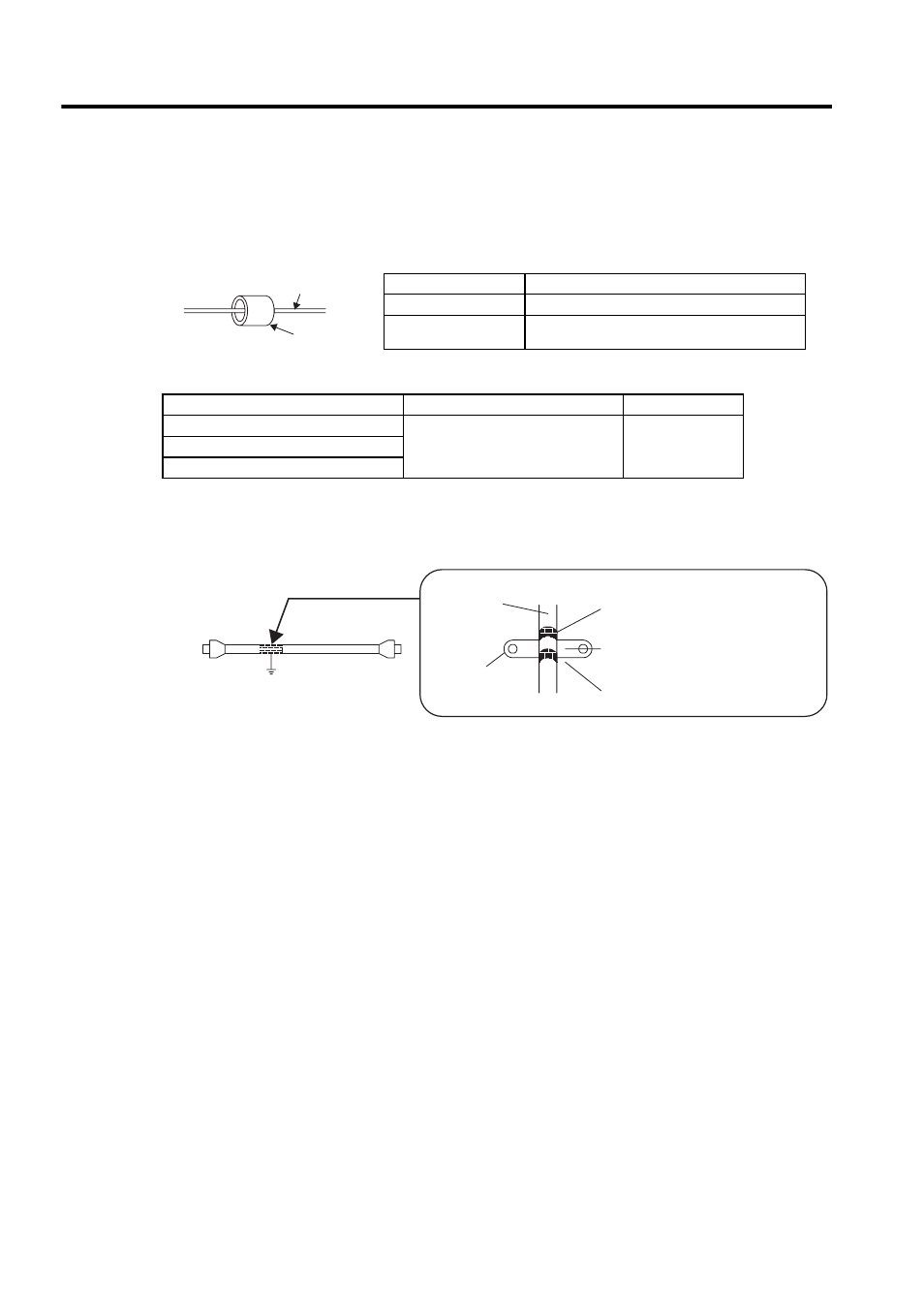
(2) Cable Core and Cable Clamp
(a) Attaching the Ferrite Core
The diagram shows one turn in the cable.
The table shows the cable and the position where the ferrite core is attached.
(b) Recommended Ferrite-core
(c) Fixing the Cable
Fix and ground the cable shield using a piece of conductive metal.
• Example of Cable Clamp
(d) Shield Box
A shield box, which is a closed metallic enclosure, should be used for shielding magnetic interference. The
structure of the box should allow the main body, door, and cooling unit to be attached to the ground. The box
opening should be as small as possible.
Cable Name
Mounting Position of the Core
Motor cable
Near the SERVOPACK and the servomotor.
Encoder cable
Near the SERVOPACK and the servomotor.
Cable
Ferrite core
Cable Name
Ferrite Core Model
Manufacturer
I/O signals cable
ESD-SR-25
NEC TOKIN
Corporation
Encoder cable
Motor cable
Host controller side
Ground plate
Cable
Cable
clamp
Shield (cable sheath stripped)
Fix and ground the cable shield
using a piece of conductive metal.
Remove paint on mounting surface.