4 speed loop gain, 5 speed loop integral time constant – Yaskawa Sigma II Series DC Power Input SGMAJ User Manual
Page 264
9.3 Manual Tuning
9-13
9
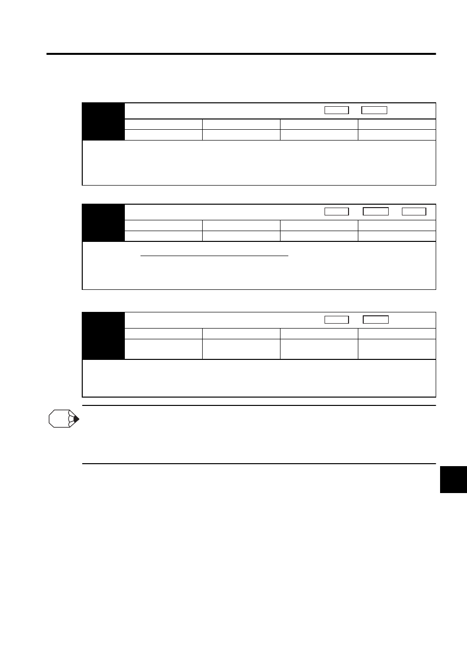
9.3.4 Speed Loop Gain
9.3.5 Speed Loop Integral Time Constant
Selecting the Speed Loop Control Method (PI Control or I-P Control)
Generally, I-P control is more effective in high-speed positioning or high-speed/precision manufacturing applications. The
position loop gain is lower than it would be in PI control, so shorter positioning times and smaller arc radii can be
achieved. On the other hand, PI control is generally used when switching to P control fairly often with a mode switch or
other method.
Pn100
Speed Loop Gain (Kv)
Setting Range
Setting Unit
Factory Setting
Setting Validation
1 to 2,000
Hz
40
Immediately
This parameter determines the responsiveness of the speed loop. If the speed loop’s responsiveness is too low, it will delay
the outer position loop and cause overshooting and vibration of the speed reference. The SERVOPACK will be most stable
and responsive when the speed loop gain is set as high as possible within the range that does not cause vibration in the
mechanical system. The value of speed loop gain is the same as the set value of Pn100 if the moment of inertia ratio in
Pn103 has been set correctly.
Speed
Position
Pn103
Moment of Inertia Ratio
Setting Range
Setting Unit
Factory Setting
Setting Validation
0 to 10,000
%
0
Immediately
The factory setting is Pn103=0. Before adjusting the servo, determine the moment of inertia ratio with the equation above
and set parameter Pn103.
Pn101
Speed Loop Integral Time Constant (Ti)
Setting Range
Setting Unit
Factory Setting
Setting Validation
15 to 51,200
(0.15 to 512.00 ms)
0.01 ms
2,000
(20.00 ms)
Immediately
The speed loop has an integral element so that the speed loop can respond to minute inputs. This integral element causes a
delay in the SERVOPACK. If the time constant is set too long, overshooting will occur, which results in a longer position-
ing settling time or responsiveness decreases.
The estimated set value for Pn101 depends on the speed loop control method with Pn10B.1, as shown below.
Speed
Position
Torque
Pn103 set value =
Motor axis conversion load moment of inertia (J
L
)
Servomotor rotor moment of inertia (J
M
)
×100(%)
Speed
Position
INFO