Un005 – Yaskawa Sigma II Series DC Power Input SGMAJ User Manual
Page 183
8 Operation
8.1.2 Trial Operation for Servomotor without Load from Host Reference
8-10
Step
Description
Check Method and Remarks
1
Configure an input signal circuit necessary for servo ON.
Connect the I/O signal connectors (CN1) in the circuit on
the previous page or equivalent to input the signal neces-
sary for servo ON. Then turn OFF the power and connect
the CN1 to the SERVOPACK.
Satisfy the following conditions:
1. Servo ON (/S-ON) input signal can be input.
2. Forward Run Prohibited (P-OT) and Reverse Run Prohibited
(N-OT) input signals are turned ON (L level). (Forward run
and reverse run are prohibited.)
3. Reference input (0V reference or 0 pulse) is not input.
To omit the external wiring, the input terminal function can be set
to “Always ON” or “Always OFF” using the input signal allocation
function of parameter. Refer to 7.3.2 Input Circuit Signal Alloca-
tion.
When the absolute encoder is used, Absolute Encoder Setup
(Fn008) operation and the SEN signal wiring can be omitted when
setting the Pn002 to n.1 (Uses absolute encoder as an incre-
mental encoder) only during trial operation.
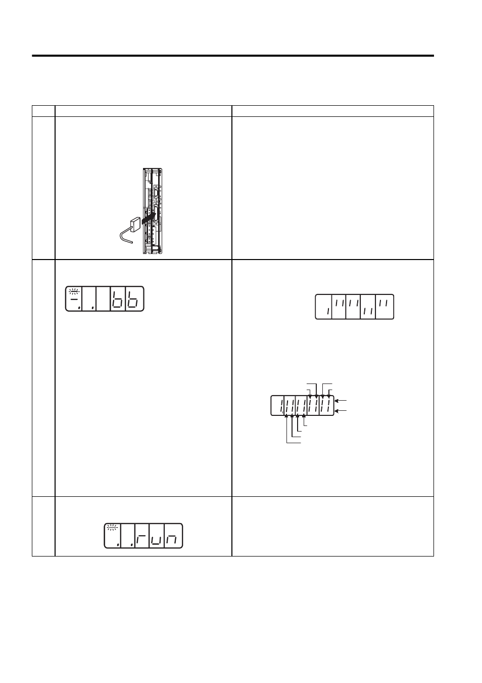
2
Turn ON the power and make sure that the digital operator
display is as shown below.
The input signal setting is not correct if the display is not the same
as on the left. Check the input signal using the Un005 (input signal
monitor) from the digital operator.
Check input signal wiring in monitor mode using the digital opera-
tor or panel operator. Refer to 7.4.1 List of Monitor Modes.
Turn ON and OFF each signal line to see if the LED monitor bit
display on the digital operator changes as shown below.
If an absolute encoder is being used, the servo will not turn ON
when the servo ON signal (/S-ON) is input unless the SEN signal is
also ON.
When the SEN signal is checked in monitor mode, the top of the
LED will light because the SEN signal is high when ON.
3
Input the /S-ON signal, then make sure that the display of
the digital operator is as shown below.
If an alarm display appears, correct it according to 10.1 Trouble-
shooting. If there is noise in the reference voltage during speed
control, the horizontal line (
−) at the far left edge of the digital
operator display may blink. Also the servomotor may turn very
slowly. Refer to 6.4 Others and take a preventive measure.
CN1
Un005 =
Input signal LED display
/P-CL
/N-CL
Top lights when input
signal is OFF (high level).
Bottom lights when input
signal is ON (low level).
/ALM-RST
/P-CON
/S-ON
P-OT
N-OT
SEN
Un005 =