3 typical main circuit wiring examples, Important – Yaskawa Sigma II Series DC Power Input SGMAJ User Manual
Page 123
6 Wiring
6.1.3 Typical Main Circuit Wiring Examples
6-4
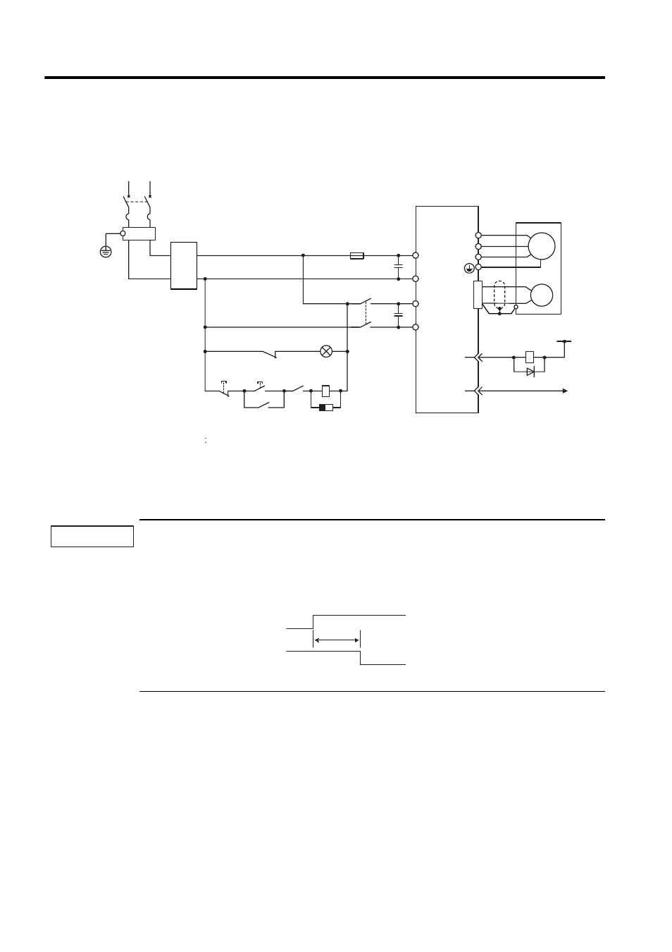
6.1.3 Typical Main Circuit Wiring Examples
Single-phase, 100/200 V
Designing a Power ON Sequence
Note the following points when designing the power ON sequence.
• Design the power ON sequence so that main circuit power supply is turned OFF when a servo alarm signal
is output. See the previous circuit figure.
• The SERVOPACK will output (1Ry is OFF) a servo alarm signal for two seconds or less when the control
power is turned ON. This is required in order to initialize the SERVOPACK.
• Select the power supply specifications for the parts in accordance with the input power supply.
OFF
ON
Main circuit
power supply
Main circuit
power supply
1QF
FIL
1KM
Molded-case circuit breaker
: Noise filter
: Magnetic contactor
1CAP
2CAP
: Capacitor for the control power supply input
: Capacitor for the main circuit power supply input
: Indicator lamp
: Surge suppressor
: Flywheel diode
: Fuse
1PL
: Relay
1Ry
1SUP
1D
1FU
C1
AC/DC
Converter
C2
L1
L2
SERVOPACK
SGDJ-
C
SGDJ-
E
U
V
W
M
PG
ALM
−
0
24
V
1Ry
ALM+
31
32
1D
1KM
1KM
1SUP
1Ry
CN1
CN4
1QF
R
T
1PL
1CAP
FIL
+24V
+
-
2CAP
1KM
1FU
+
-
IMPORTANT
Power supply
Servo alarm (ALM)
output signal
2.0 s max.