Bypass start-up procedure, Precautions for connected machinery, 5 start-up procedure – Yaskawa AC Drive Z1000 Bypass Technical Manual User Manual
Page 105
11.
Record all other connections to the Z1000 Bypass by terminal number to determine if special programming of any of
the following is required:
Multi-function Digital Inputs – Bypass control board TB2 (A2)
Multi-function Digital Outputs – Bypass control board TB1 (A2)
Analog Inputs – Drive control board (A1)
Analog Outputs – Drive control board (A1)
Differential PI control – Bypass control board (A2)
Serial Communications – Bypass control board TB3 (A2)
12.
Verify that all control wiring is run in separate conduit from motor or line power and route digital output wiring exceeding
24 V in conduit separate from other control wiring.
13.
Verify that the building automation system logic is ready for the start, stop, and speed command functions.
n
Precautions for Connected Machinery
WARNING! Sudden Movement Hazard. Clear all personnel from the drive, motor, and machine area before applying power. System may
start unexpectedly upon application of power, causing death or serious injury.
WARNING! Sudden Movement Hazard. Always check the operation of any fast stop circuits after they are wired. Fast stop circuits are
required to provide safe and quick shutdown of the drive. Prepare to initiate an emergency stop during the test run. Operating a drive with
untested emergency circuits could result in death or serious injury.
• The motor should come to a complete stop without problems.
• Connect the load and machinery to the motor.
• Fasten all installation screws properly and check that the motor and connected machinery are held in place.
u
Bypass Start-Up Procedure
, replace all Z1000 Bypass and drive covers. Connect one end of
the HOA keypad cable to the Bypass control board A2 and one end to the door-mounted HOA keypad.
Step
Display/Result
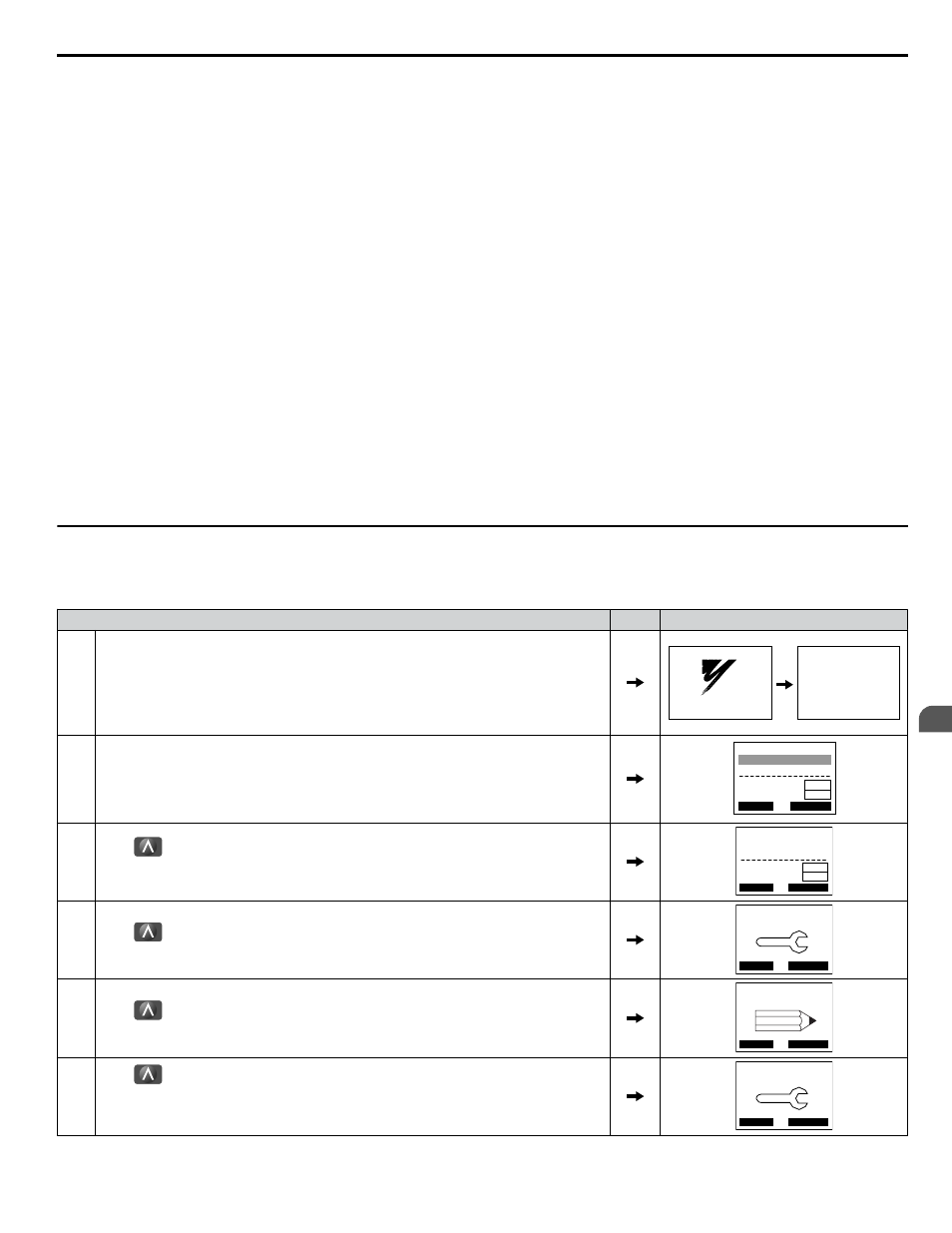
1.
Remove any power source lockouts on the Z1000 Bypass then turn the main input disconnect
handle clockwise to energize the Z1000 Bypass.
Refer to Input Disconnect Switch on page
for details.
Use a multimeter to check all three-phase voltages for proper levels and balance and record
these levels for future reference.
During this sequence, the control logic will briefly (< 3 s) perform a self-test to ensure proper
operation.
YASKAWA
Z1000
Z1000 Bypass
Control
(VST000291)
2.
The keypad will now display the main startup screen showing that the Z1000 Bypass is in
Drive mode and currently OFF. It also shows that the Bypass is in “AUTO” mode while
displaying the frequency reference.
DRV-OFF
U1-01= 0.00Hz
U1-02= 0.00Hz
U1-03= 0.00 A
Freq Ref (AUTO)
LSEQ
LREF
RLY
DRV/BYP
3.
Press
one time to display the Monitor Menu.
All available drive and bypass monitors can be viewed from this menu.
for a complete list of monitors.
DRV-OFF
U1-01= 60.00Hz
U1-02= 0.00Hz
U1-03= 0.00 A
Monitor Menu
LSEQ
LREF
RLY DRV/BYP
4.
Press
one time to display the Quick Settings Menu.
This is a condensed parameter set specifically selected for the initial drive start-up.
DRV-OFF
Quick Setting
DATA
HELP
5.
Press
one time to display the Programming Menu.
All available drive and bypass parameters can be accessed through this menu.
DRV-OFF
Programming
DATA
HELP
6.
Press
one time to display the Auto-Tuning Menu.
The Auto-Tuning function tunes the drive set-up to the characteristics of the motor to which
it is applied. Auto-Tuning is essential if bi-directional Speed Search is required and enabled
for the application.
DRV-OFF
Auto-Tuning
DATA
HELP
Auto
4.5 Start-Up Procedure
YASKAWA ELECTRIC SIEP YAIZ1B 01D YASKAWA AC Drive – Z1000 Bypass Technical Manual
105
4
Start-Up Programming & Operation