Refer to, Connect control wires as shown in, Figure 3.34 – Yaskawa AC Drive Z1000 Bypass Technical Manual User Manual
Page 81: Figure 3.35
A
B
C
D
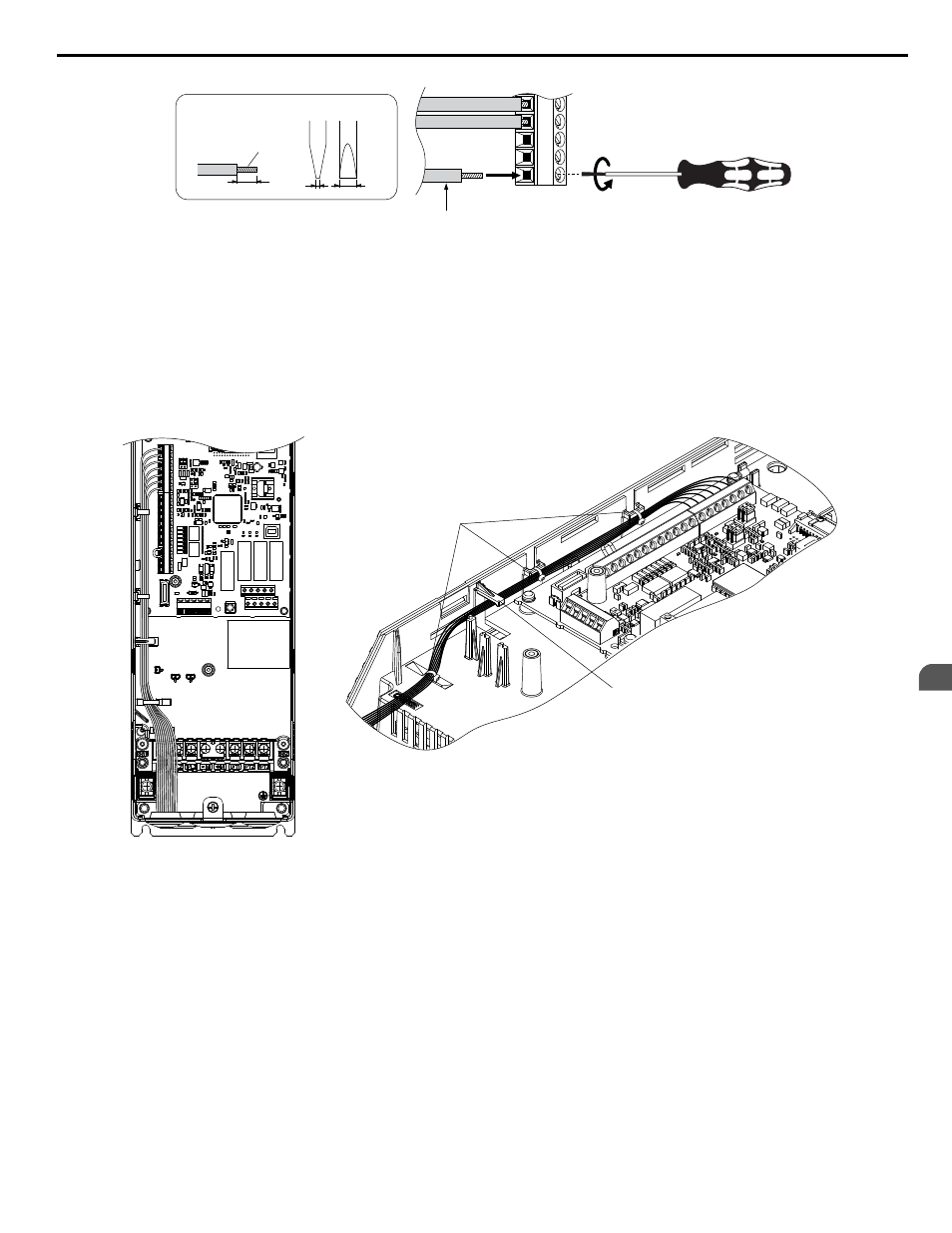
Preparing wire
terminal ends
0.4
2.5
A – Loosen screw to insert wire.
B – Single wire or stranded wire
C – Avoid fraying wire strands when
stripping insulation from wire. Strip
length 5.5 mm.
D – Blade depth of 0.4 mm or less
Blade width of 2.5 mm or less
Figure 3.34 Terminal Wiring Guide
Use the cable tie holes and cable hooks when wiring control terminals.
Note:
Take proper precautions when wiring the cables so that the front covers will easily fit back onto the drive. Make sure cables are not pinched
between the front covers and the drive when replacing the covers.
A
B
A – Cable tie hole
B – Cable hook
Figure 3.35 Control Terminal Wiring (Models Z1B1D002 to D030 and B001 to B027)
3.5 Control Circuit Wiring
YASKAWA ELECTRIC SIEP YAIZ1B 01D YASKAWA AC Drive – Z1000 Bypass Technical Manual
81
3
Electrical Installation