Wiring the drive control circuit terminal – Yaskawa AC Drive Z1000 Bypass Technical Manual User Manual
Page 80
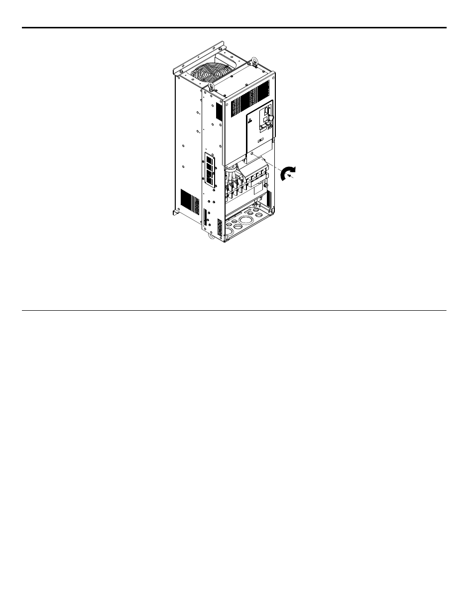
Figure 3.33 Tighten the Installation Screw to Lock the Cover into Place (Models Z1B1D143 to D273 and B124 to B302)
n
Top Protective Cover
Drives mounted on top of Z1000 Bypass enclosures are designed to NEMA Type 1 specifications with a protective cover on
the top. Removing this top protective cover voids the NEMA Type 1 protection. Do not remove the top protective cover.
u
Wiring the Drive Control Circuit Terminal
This section describes the proper procedures and preparations for wiring the control terminals.
WARNING! Electrical Shock Hazard. Do not remove covers or touch the circuit boards while the power is on. Failure to comply could result
in death or serious injury.
NOTICE: Separate control circuit wiring from main circuit wiring (terminals R/L1, S/L2, T/L3, -M, +M, -, +1, +3, U/T1, V/T2, W/T3) and other
high-power lines. Improper wiring practices could result in drive malfunction due to electrical interference.
NOTICE: Separate wiring for digital output terminals MA, MB, MC, and M1 to M6 from wiring to other control circuit lines. Improper wiring
practices could result in drive or equipment malfunction or nuisance trips.
NOTICE: Use a class 2 power supply when connecting to the control terminals. Improper application of peripheral devices could result in
drive performance degradation due to improper power supply. Refer to NEC Article 725 Class 1, Class 2, and Class 3 Remote-Control,
Signaling, and Power Limited Circuits for requirements concerning class 2 power supplies.
NOTICE: Insulate shields with tape or shrink tubing to prevent contact with other signal lines and equipment. Improper wiring practices could
result in drive or equipment malfunction due to short circuit.
NOTICE: Connect the shield of shielded cable to the appropriate ground terminal. Improper equipment grounding could result in drive or
equipment malfunction or nuisance trips.
Terminal Wiring Guide on page 81
for details. Prepare the ends of the control circuit wiring as shown in
NOTICE: Do not tighten screws beyond the specified tightening torque. Failure to comply may result in erroneous operation, damage to the
terminal block, or cause a fire.
NOTICE: Use shielded twisted-pair cables as indicated to prevent operating faults. Improper wiring practices could result in drive or
equipment malfunction due to electrical interference.
Connect control wires as shown in
.
Yaskawa recommends Phoenix Contact screwdriver model SZF 0-0.4 x 2.5 or equivalent to wire the terminal block.
3.5 Control Circuit Wiring
80
YASKAWA ELECTRIC SIEP YAIZ1B 01D YASKAWA AC Drive – Z1000 Bypass Technical Manual