Z2: bypass control input/output – Yaskawa AC Drive Z1000 Bypass Technical Manual User Manual
Page 346
No.
(Addr.
Hex)
Name
LCD Display
Description
Values
Page
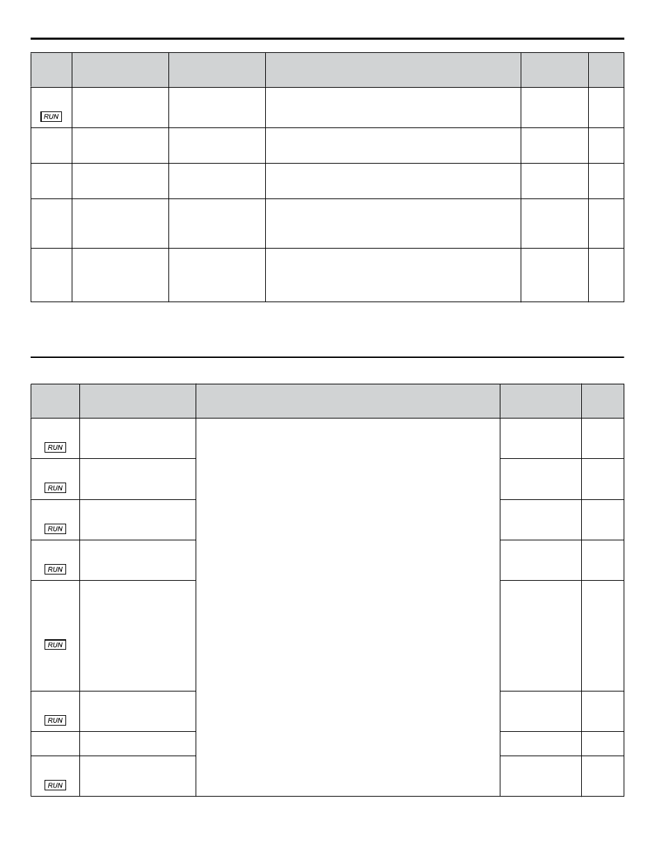
Z1-40
(85ED) Auto Transfer Wait
Time
Auto Xfer Wait T
If Auto Transfer is enabled and a drive fault is detected, the
bypass controller will wait this length of time before switching
to bypass.
Default: 0.0 s
Min.: 0.0
Max.: 300.0
Z1-41
(85EE)
<3>
Hand Speed Reference
Selection
Hand Spd Ref Sel
Selects the frequency reference source when in Hand Mode.
0: Parameter Z1-09
1: Analog
Default: 0
Range: 0, 1
Z1-50
(85F7)
<3>
Bypass Unbalanced
Current Detection
Level
Byp Unbal Level
Sets the current unbalance level between phases when operating
in Bypass Mode.
Default: 25.0%
Min.: 5.0
Max.: 25.0
Z1-51
(85F8)
<3>
Bypass Unbalance Trip
Time Detection Level
Byp Unbal Time
Sets the trip time for an unbalance condition operating in Bypass
Mode.
Note:
Setting this parameter to 0.0 will disable unbalance
detection.
Default: 5.0 s
Min.: 0.0
Max.: 30.0
Z1-52
(85F9)
<3>
Bypass Phase Rotation Byp Phs Rotation
Determines the action to take when Bypass Mode phase rotation
is incorrect
0: Disabled
1: Alarm
2: Fault
Default: 1
Range: 0 to 2
<1> Default is 0 in bypass controller software versions VST800297 and earlier.
<2> Values are given in Hz, but actual values are dependent upon unit settings using drive parameters o1-03, o1-09, o1-10, and o1-11.
<3> Available in bypass controller software versions VST800298 and later.
u
Z2: Bypass Control Input/Output
No.
(Addr.
Hex)
Name
Description
Values
Page
Z2-01
(8563)
Digital Input 1 Function
Select
0: Unused (Available for Serial Comms)
3: DRV Multi-Function Input S3 (H1-03 Setting)
4: DRV Multi-Function Input S4 (H1-04 Setting)
5: DRV Multi-Function Input S5 (H1-05 Setting)
6: DRV Multi-Function Input S6 (H1-06 Setting)
7: DRV Multi-Function Input S7 (H1-07 Setting)
21: Run (AUTO Mode)
22: Run Enable (Safety)
23: Run Interlock (BAS)
24: Remote Transfer to Bypass
25: Smoke Purge Bypass Run to Destruction
26: Smoke Purge Drive Run to Destruction at Smoke Purge Preset Speed (See
Z1-10). Bypass controller will stay in this state even if the drive faults or is
unavailable.
27: Motor OR Select (2-Motor OR function; 0/1 for Motor 1/2. Behavior
defined by Z1-11)
28: Motor AND Select (2-Motor AND function; 0/1 for 1/2 motor. If 1 motor,
then look to Motor OR input for selected motor. Behavior defined by Z1-11)
29: Motor 1 Overload Contact. When input is open, declare an OL Fault, issue
an EF0 fault to the drive, delay per EF0 Fault Delay Time (Z1-30), and open
Drive Output (K2) and Bypass (K3) contactors.
30: Motor 2 Overload Contact. When input is open, declare an OL Fault, issue
an EF0 fault to the drive, delay per EF0 Fault Delay Time (Z130), and open
Drive Output (K2) and Bypass (K3) contactors.
31: HAND Select
32: AUTO Select
33: DRIVE/BYPASS Select (0/1 for Drive/Bypass)
34: Fault Reset
35: External Fault (EF0)
36: External Fault (EFB)
37: Run Reverse
Default: 21
Range: 0 to 36
Z2-02
(8564)
Digital Input 2 Function
Select
Default: 22
Range: 0 to 36
Z2-03
(8565)
Digital Input 3 Function
Select
Default: 23
Range: 0 to 36
Z2-04
(8566)
Digital Input 4 Function
Select
Default: 24
Range: 0 to 36
Z2-05
(8567)
Digital Input 5 Function
Select
Default: 25
Range: 0 to 36
Z2-06
(8568)
Digital Input 6 Function
Select
Default: 0
Range: 0 to 36
Z2-07
(8569)
Digital Input 7 Function
Select
Default: 0
Range: 0 to 36
Z2-08
(856A)
Digital Input 8 Function
Select
Default: 29
Range: 0 to 36
B.14 Z: Bypass Parameters
346
YASKAWA ELECTRIC SIEP YAIZ1B 01D YASKAWA AC Drive – Z1000 Bypass Technical Manual