Bypass analog outputs, Serial communications – Yaskawa AC Drive Z1000 Bypass Technical Manual User Manual
Page 72
u
Bypass Analog Outputs
There are two analog outputs that can be configured for a signal level of 0 to 10 Vdc or 4 to 20 mA. The signal level is controlled
by the position of jumpers J2 and J3 on Control PCB A2 and by the values set to drive parameters H4-07 and H4-08.
u
Serial Communications
Refer to BACnet Communications on page 355
Refer to MEMOBUS/Modbus Communications on page 375
for details
depending on the applicable serial communications protocol.
n
Serial Communication Terminals
Table 3.9 Control Circuit Terminals: Serial Communications
Type
Name
Description
Notes
MEMOBUS/Modbus or
BACnet
Communication
IG5
Isolated ground
Ground reference for RS-485 signals. This is an isolated ground
used only for communications and may be used in certain
circumstances to connect to other communication devices floating
ground references.
TXRX+
(+) Differential communication signal
RS-485 signal levels
TXRX-
(-) Differential communication signal
SHIELD Shield tie point
Connected to chassis ground
n
Bypass and Drive Control Circuit Wire Size and Torque Specifications
Select appropriate wire type and gauges from
. For simpler and more reliable wiring, use crimp ferrules on the wire
for ferrule terminal types and sizes.
Table 3.10 Bypass and Drive Control Circuit Gauge and Torque Values
Terminal
Screw
Size
Tightening
Torque
N
•m
(lb. in)
Bare Wire Terminal
Ferrule-Type Terminal
Wire Type
Applicable
wire size
mm
2
(AWG)
Recomm.
wire size
mm
2
(AWG)
Applicable
wire size
mm
2
(AWG)
Recomm.
wire size
mm
2
(AWG)
DO-7, DO-8, DO-9,
DO-10
DI-1, DI-2, DI-3, DI-4,
DI-5, DI-6, DI-7, DI-8,
IG24
IG5, TXRX+, TXRX-,
SHIELD
M3
0.5 to 0.6
(4.4 to 5.3)
Stranded wire:
0.2 to 1.0
(24 to 16)
Solid wire:
0.2 to 1.5
(24 to 16)
0.75 (18)
0.25 to 0.5
(24 to 20)
0.5 (20)
Shielded wire,
etc.
+V, A1, A2, AC
FM, AM, AC
R+, R-, S+, S-, IG
M3
0.5 to 0.6
(4.4 to 5.3)
Stranded wire:
0.2 to 1.0
(24 to 16)
Solid wire:
0.2 to 1.5
(24 to 16)
0.75 (18)
0.25 to 0.5
(24 to 20)
0.5 (20)
Shielded wire,
etc.
n
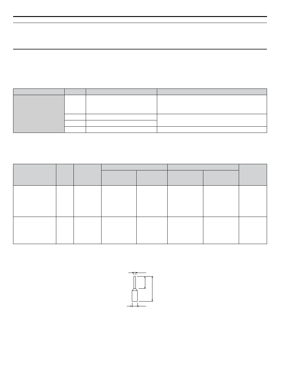
Ferrule-Type Wire Terminals
Yaskawa recommends using CRIMPFOX 6, a crimping tool manufactured by PHOENIX CONTACT, to prepare wire ends
with insulated sleeves before connecting to the drive. See
d1
d2
8 mm
L
Figure 3.21 Ferrule Dimensions
3.5 Control Circuit Wiring
72
YASKAWA ELECTRIC SIEP YAIZ1B 01D YASKAWA AC Drive – Z1000 Bypass Technical Manual