Wiring the main input circuit – Yaskawa AC Drive Z1000 Bypass Technical Manual User Manual
Page 67
A
B
B
C
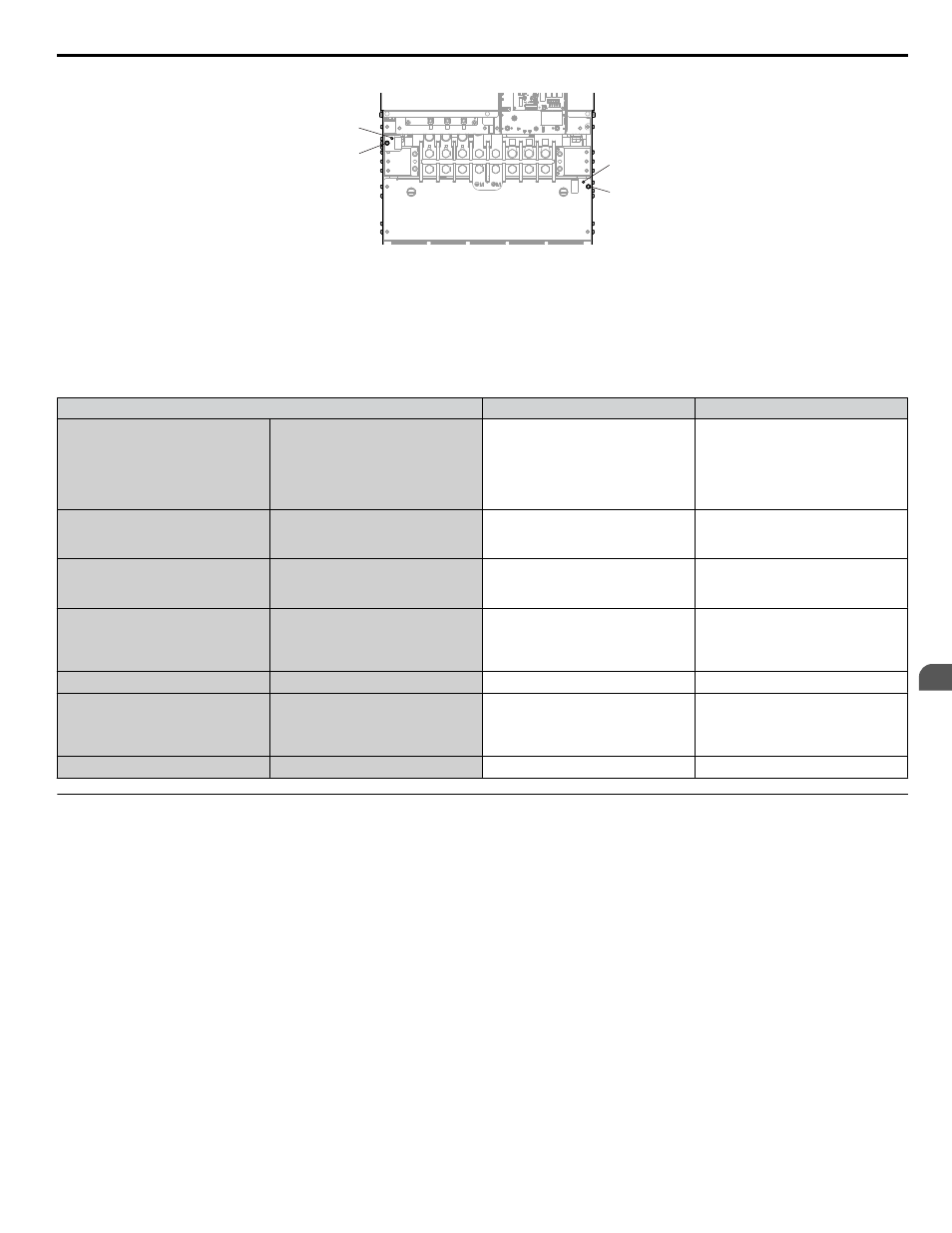
A – SW1 (ON)
B – Screw (OFF)
C – SW2 (ON)
Figure 3.16 EMC Filter Switch Location (Model Z1B1B302)
.
NOTICE: Do not use screws of different sizes in SW1 and SW2. Failure to comply may cause overheating.
Table 3.6 SW1/SW2 Screw Sizes and Tightening Torques
Bypass Model Z1B1
SW1/SW2 Screw Size
Tightening Torque
D002
D003
D004
D007
D010
D016
B001
B002
B003
B004
B007
B011
M3 × 16
0.5 to 0.6 N
•m
D024
D030
B014
B021
B027
M3 × 16
0.5 to 0.6 N
•m
D046
D059
B034
B040
B52L
M3 × 16
0.5 to 0.6 N
•m
D074
D088
D114
B052
B065
B077
B096
M5 × 30
2 to 2.5 N
•m
–
B124
M5 × 25
2 to 2.5 N
•m
D143
D169
D211
D273
B156
B180
B240
M5 × 25
2 to 2.5 N
•m
–
B302
M5 × 25
2 to 2.5 N
•m
u
Wiring the Main Input Circuit
WARNING! Electrical Shock Hazard. Shut off the power supply to the drive before wiring the main circuit terminals. Failure to comply may
result in death or serious injury.
Wire the main circuit terminals after the terminal board has been properly grounded.
3.4 Input and Output Power Wiring Connections
YASKAWA ELECTRIC SIEP YAIZ1B 01D YASKAWA AC Drive – Z1000 Bypass Technical Manual
67
3
Electrical Installation