H4: analog outputs, H5: memobus/modbus serial communication – Yaskawa AC Drive Z1000 Bypass Technical Manual User Manual
Page 323
u
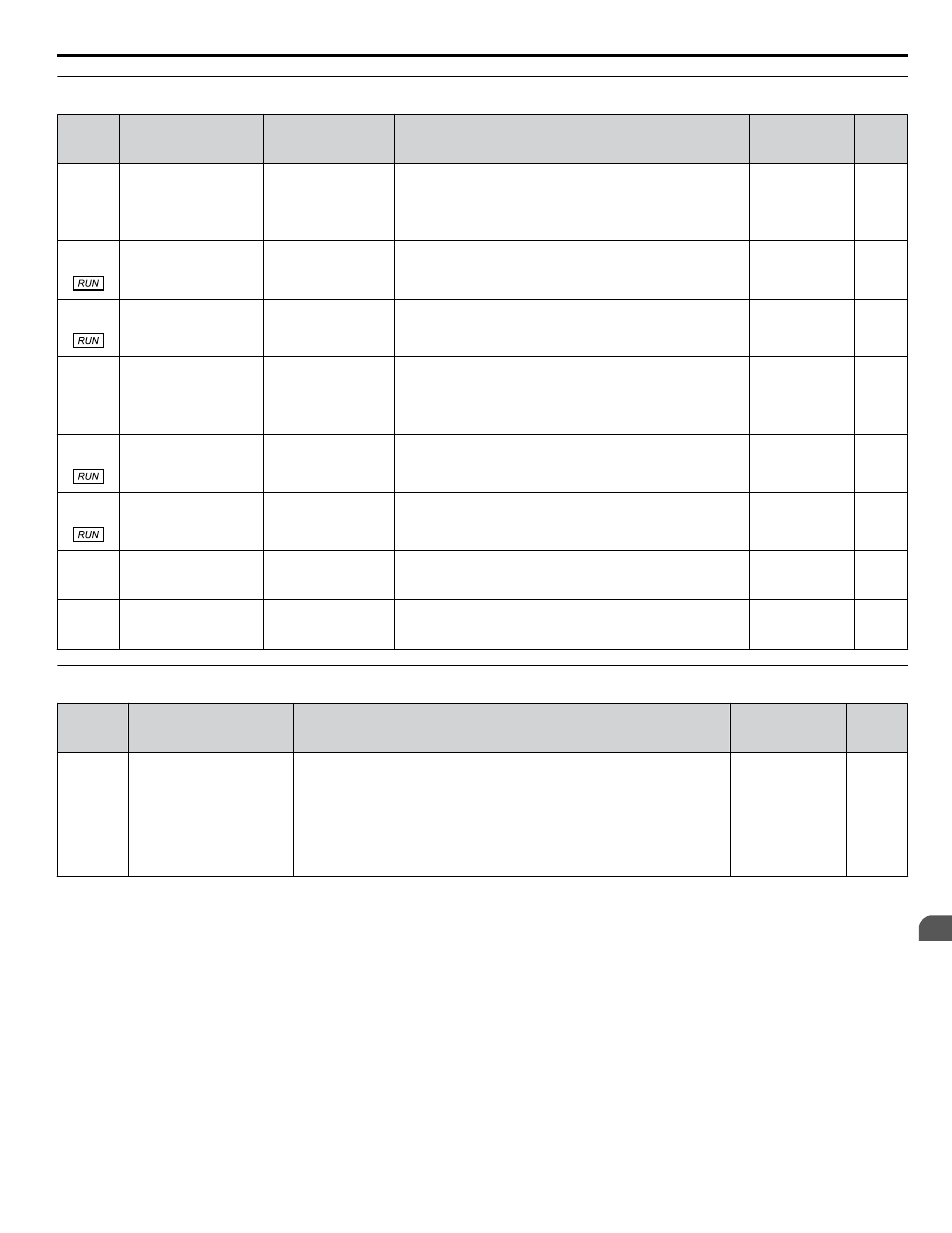
H4: Analog Outputs
No.
(Addr.
Hex)
Name
LCD Display
Description
Values
Page
H4-01
(41D)
Multi-Function Analog
Output Terminal FM
Monitor Selection
Term FM FuncSel
Selects the data to be output through multi-function analog
output terminal FM.
Set the desired monitor parameter to the digits available in
Uo-oo.
For example, enter “103” for U1-03.
Default: 102
Range: 000 to
621
H4-02
(41E)
Multi-Function Analog
Output Terminal FM
Gain
Terminal FM Gain
Sets the signal level at terminal FM that is equal to 100% of the
selected monitor value.
Default: 100.0%
Min.: -999.9
Max.: 999.9
H4-03
(41F)
Multi-Function Analog
Output Terminal FM
Bias
Terminal FM Bias
Sets the signal level at terminal FM that is equal to 0% of the
selected monitor value.
Default: 0.0%
Min.: -999.9
Max.: 999.9
H4-04
(420)
Multi-Function Analog
Output Terminal AM
Monitor Selection
Terminal AM Sel
Selects the data to be output through multi-function analog
output terminal AM.
Set the desired monitor parameter to the digits available in
Uo-oo.
For example, enter “103” for U1-03.
Default: 103
Range: 000 to
621
H4-05
(421)
Multi-Function Analog
Output Terminal AM
Gain
Terminal AM Gain
Sets the signal level at terminal AM that is equal to 100% of
the selected monitor value.
Default: 50.0%
Min.: -999.9
Max.: 999.9
H4-06
(422)
Multi-Function Analog
Output Terminal AM
Bias
Terminal AM Bias
Sets the signal level at terminal AM that is equal to 0% of the
selected monitor value.
Default: 0.0%
Min.: -999.9
Max.: 999.9
H4-07
(423)
Multi-Function Analog
Output Terminal FM
Signal Level Selection
Term FM Lvl Sel
0: 0 to 10 V
0: 0-10 VDC
2: 4 to 20 mA
2: 4-20 mA
Default: 0
Range: 0, 2
H4-08
(424)
Multi-Function Analog
Output Terminal AM
Signal Level Selection
Term AM Lvl Sel
0: 0 to 10 V
0: 0-10 VDC
2: 4 to 20 mA
2: 4-20 mA
Default: 0
Range: 0, 2
u
H5: MEMOBUS/Modbus Serial Communication
No.
(Addr.
Hex)
Name
Description
Values
Page
H5-04
(428)
<1>
Stopping Method after
Communication Error (CE)
Serial Fault Sel
Note:
The function associated with this parameter is only used
internally and is not related to customer serial communications.
0: Ramp to Stop
0: Ramp to Stop
1: Coast to Stop
1: Coast to Stop
2: Fast-Stop
2: Fast-Stop
3: Alarm only
3: Alarm Only
4: Run at d1-04
4: Alarm (d1-04)
Default: 3
Range: 0 to 4
<1> Parameter is only available in bypass controller software versions VST800297 and earlier.
B.8 H Parameters: Multi-Function Terminals
YASKAWA ELECTRIC SIEP YAIZ1B 01D YASKAWA AC Drive – Z1000 Bypass Technical Manual
323
B
Parameter List