Yaskawa AC Drive Z1000 Bypass Technical Manual User Manual
Page 71
Type
Signal Name
Description
Specification
Digital Outputs
120 Vac
DO-1
Digital Output 1
(Factory use only) 120 Vac, 66 VA sealed, 1650 inrush
DO-2
Digital Output 2
DO-3
Digital Output 3
DO-4
Digital Output 4
DO-5
Digital Output 5
Digital Outputs
DO-6
Digital Output 6
Relay, dry contact form C, 30 Vdc or 120 Vac,
DO-6 (factory use only), 3.7 Amp 360 VA,
DO-7 to DO-10 for customer use, 2 Amp
DO-7
Digital Output 7
DO-8
Digital Output 8
DO-9
Digital Output 9
DO-10
Digital Output 10
lists the available control circuit input terminals on the drive. Text in parenthesis indicates the default setting for
each multi-function input.
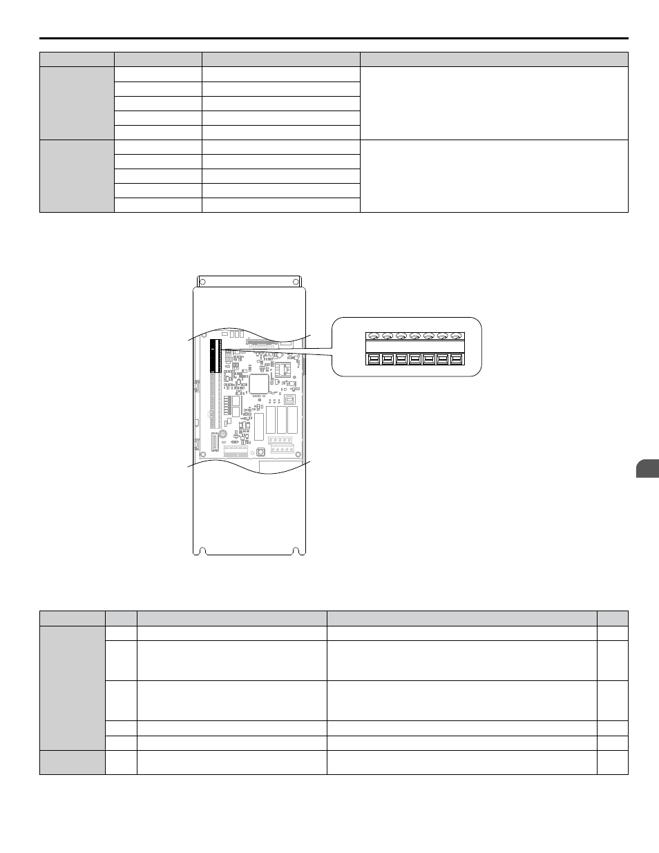
The drive control circuit terminals on Terminal Board A1 are arranged as shown in
TB3
+V AC A1 A2 FM AM AC
Figure 3.20 Control Circuit Terminal Board A1 Arrangement
Table 3.8 Drive Control Circuit Terminal Board A1
Type
No.
Terminal Name (Function)
Function (Signal Level) Default Setting
Page
Frequency
Reference
Inputs
+V
Power supply for analog inputs
10.5 Vdc (maximum allowable current 20 mA)
A1
Multi-function analog input 1
(Frequency reference bias)
• 0 to 10 Vdc/100% (input impedance: 20 kΩ)
• 4 to 20 mA/100%, 0 to 20 mA/100% (input impedance: 250 Ω)
• Voltage or current input must be selected by Jumper S1 and H3-01.
A2
Multi-function analog input 2
(Frequency reference bias)
• 0 to 10 Vdc/100% (input impedance: 20 kΩ)
• 4 to 20 mA/100%, 0 to 20 mA/100% (input impedance: 250 Ω)
• Voltage or current input must be selected by Jumper S1 and H3-09.
AC
Frequency reference common
0 V
FE
Ground for shielded lines and option cards
–
–
External Power
Supply
+P
External Power Supply
24 V (Max. 150 mA)
–
3.5 Control Circuit Wiring
YASKAWA ELECTRIC SIEP YAIZ1B 01D YASKAWA AC Drive – Z1000 Bypass Technical Manual
71
3
Electrical Installation