Bypass component descriptions, Bypass front control panel, 4 bypass component descriptions – Yaskawa AC Drive Z1000 Bypass Technical Manual User Manual
Page 31: Input disconnect switch, Contactors
1.4 Bypass Component Descriptions
u
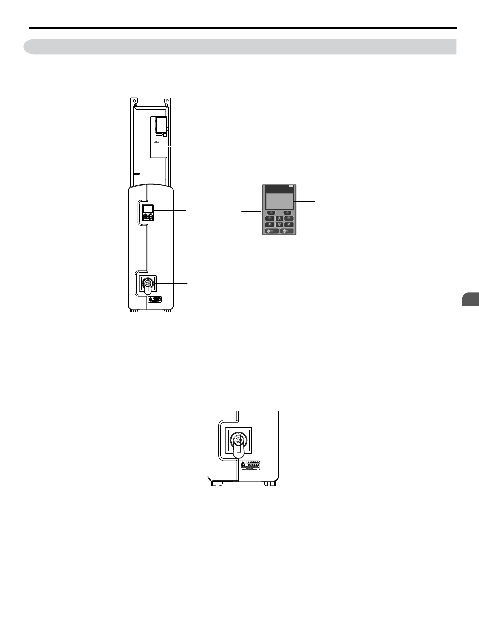
Bypass Front Control Panel
The external appearance and component names of the Z1000 Bypass are shown in
HOA keypad
Disconnect handle
Z1000 Drive
F2
F1
ESC
M
M
AUTO
OFF
ENTER
RESET
ALM
DIGITAL OPERATOR JVOP-183
HAND
Alpha-numeric
LCD display
Figure 1.3 Z1000 Bypass Control Panel with Keypad Operator Controls
Refer to Using the HOA Keypad on page 91
for details on the HOA keypad.
n
Input Disconnect Switch
Electrically located on the input power side of the bypass, the door mounted rotary input disconnect switch provides a means
of disconnecting the bypass from line power for equipment maintenance. The disconnect must be in the OFF position to open
the bypass enclosure door. When opened, the handle can be locked in the OFF position using a padlock.
Branch short circuit protection for the bypass must be supplied by the customer.
Figure 1.4 Disconnect Handle Shown in the OFF position
n
Contactors
The Z1000 Bypass is a 2-contactor or 3-contactor bypass circuit employing IEC rated contactors in an electrically interlocked
arrangement to allow mutually exclusive operation in Drive or Bypass modes.
The control logic and “soft start” characteristic of the drive limit the drive input and output contactors to motor FLA current
or less. For this reason, the drive output contactor has a lower current rating than the bypass contactor. The bypass contactor
is exposed to motor inrush current (LRA) when starting the motor across-the-line and therefore requires a higher current rating.
1.4 Bypass Component Descriptions
YASKAWA ELECTRIC SIEP YAIZ1B 01D YASKAWA AC Drive – Z1000 Bypass Technical Manual
31
1
Receiving