Memobus/modbus data table, Command data, D.9 memobus/modbus data table – Yaskawa AC Drive Z1000 Bypass Technical Manual User Manual
Page 388
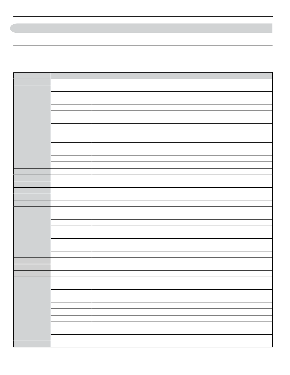
D.9 MEMOBUS/Modbus Data Table
The tables below list all MEMOBUS/Modbus data.
u
Command Data
It is possible to both read and write command data.
Note:
Bits that are not used should be set to 0. Refrain from writing to reserved registers.
Register No.
Contents
0000H
Reserved
0001H
Operation Commands and Multi-function Inputs
bit 0
Reserved
bit 1
Reserved
bit 2
External Fault (EF0)
bit 3
Fault Reset
bit 4
Reserved
bit 5
Reserved
bit 6
Multi-Function Input 3
bit 7
Multi-Function Input 4
bit 8
Multi-Function Input 5
bit 9
Multi-Function Input 6
bit A
Multi-Function Input 7
bit B to F
Reserved
0002H
Reserved
Reserved
0003H
V/f Gain
0004H, 0005H
Reserved
0006H
PI Target, 0.01% units, signed
0007H
Analog Output Terminal FM Setting (10 V / 4000 H)
0008H
Analog Output Terminal AM Setting (10 V / 4000 H)
0009H
Settings for Multi-Function Digital Outputs
bit 0
Multi-Function Contact Output 1 (terminal M1-M2)
bit 1
Multi-Function Contact Output 2 (terminal M3-M4)
bit 2
Multi-Function Contact Output 3 (terminal M5-M6)
bit 3 to 5
Reserved
bit 6
Enables the function in bit 7
bit 7
Fault Contact Output (terminal MA/MB-MC)
bit 8 to F
Reserved
000AH to 000CH Reserved
000DH
PI2 Setpoint
000EH
Reserved
000FH
Control Selection Setting
bit 0
Reserved
bit 1
PI Setpoint Input
bit 2, bit 3
Reserved
bit 4
PI2 Target Input (enables the setting from MEMOBUS/Modbus)
bit 5 to B
Reserved
bit C
Enable Terminal S5 Input for Broadcast Data
bit D
Enable Terminal S6 Input for Broadcast Data
bit E
Enable Terminal S7 Input for Broadcast Data
bit F
Reserved
0010H to 001FH
Reserved
D.9 MEMOBUS/Modbus Data Table
388
YASKAWA ELECTRIC SIEP YAIZ1B 01D YASKAWA AC Drive – Z1000 Bypass Technical Manual