Input signal allocation – Yaskawa FSP Amplifier User Manual
Page 114
FSP Amplifier User’s Manual
Chapter 5: Parameter Settings and Functions
5-47
The following parameter is used to enable input signal allocation.
Parameter Signal
Setting
Control
Mode
Pn50A.0
Input Signal Allocation Mode
Default Setting: 0
Speed, Torque, and
Position Control
Pn50A.0 Setting
Description
0
Sets the input signals to use default values.
1
Enables any sequence input signal settings.
Note:
The default setting for parameter Pn50A.0 is 0. Functions and applications in this manual are generally
described for the factory defaults.
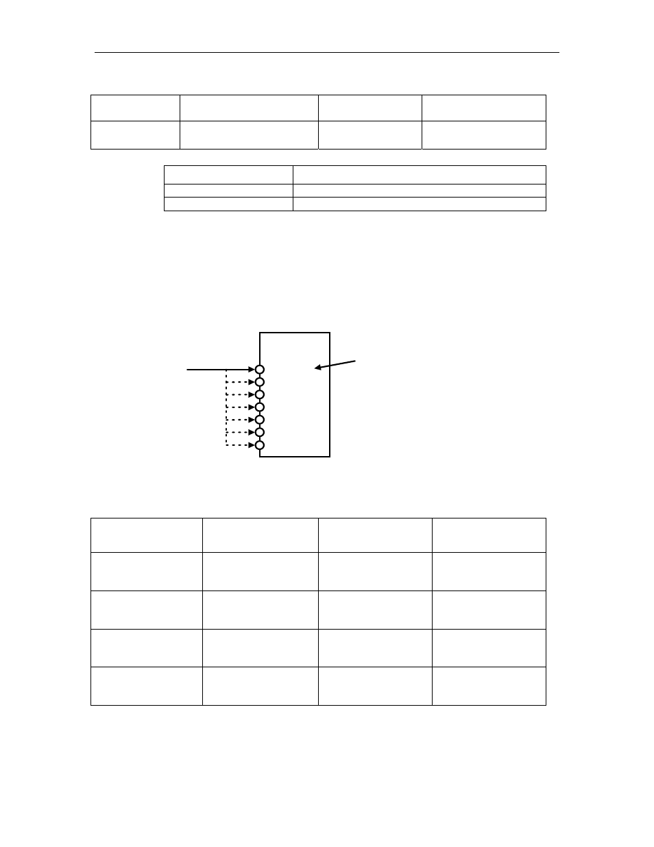
Input Signal Allocation
The following signal can be allocated when Pn50A.0 is set to 1.
/S-ON
Determines
terminal
allocation
for input
signals.
CN1
XtraDrive
40 (SI0)
44 (SI4)
45 (SI5)
46 (SI6)
41 (SI1)
42 (SI2)
43 (SI3)
CN1-40 is factory set for
the /S-ON input signal.
Any terminal from CN1-40 to
46 can be allocated to the
/S-ON signal through the
Pn50A.1 setting.
FSP Amplifier
The following table shows the parameter default settings for input settings
1 to 4.
Parameter Signal Setting
Control
Mode
Pn50A
Input Signal Selection 1
Default Setting: 2100
Speed, Torque, and
Position Control
Pn50B
Input Signal Selection 2
Default Setting: 6543
Speed, Torque, and
Position Control
Pn50C
Input Signal Selection 3
Default Setting: 8888
Speed, Torque, and
Position Control
Pn50D
Input Signal Selection 4
Default Setting: 8888
Speed, Torque, and
Position Control
Select the input terminal on the CN1 connector that will be used for all
input signals.